Implementation of Advance Technology for Priority based energy distribution management system
advertisement
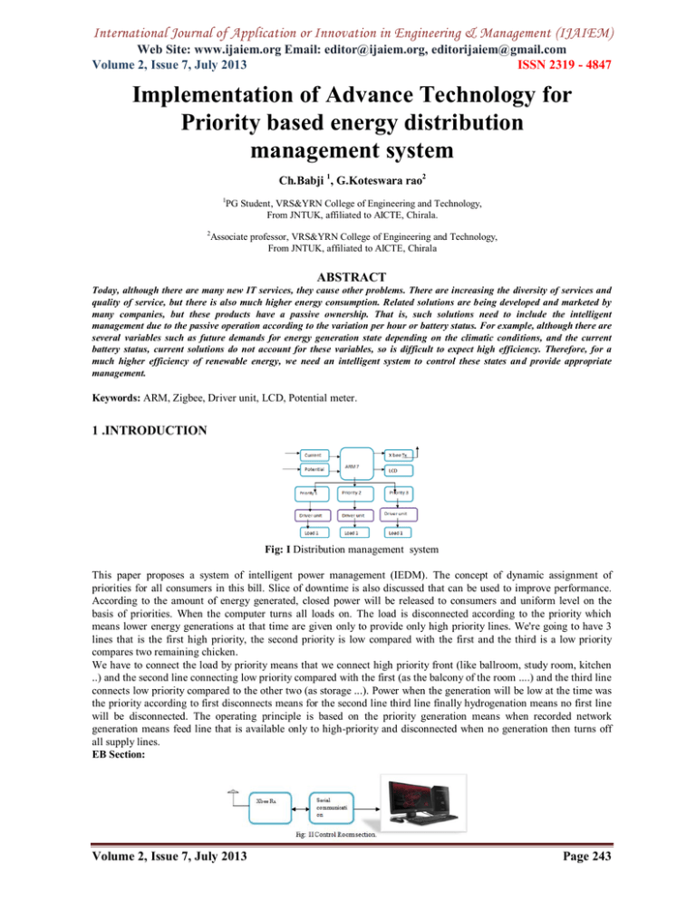
International Journal of Application or Innovation in Engineering & Management (IJAIEM) Web Site: www.ijaiem.org Email: editor@ijaiem.org, editorijaiem@gmail.com Volume 2, Issue 7, July 2013 ISSN 2319 - 4847 Implementation of Advance Technology for Priority based energy distribution management system Ch.Babji 1, G.Koteswara rao2 1 PG Student, VRS&YRN College of Engineering and Technology, From JNTUK, affiliated to AICTE, Chirala. 2 Associate professor, VRS&YRN College of Engineering and Technology, From JNTUK, affiliated to AICTE, Chirala ABSTRACT Today, although there are many new IT services, they cause other problems. There are increasing the diversity of services and quality of service, but there is also much higher energy consumption. Related solutions are being developed and marketed by many companies, but these products have a passive ownership. That is, such solutions need to include the intelligent management due to the passive operation according to the variation per hour or battery status. For example, although there are several variables such as future demands for energy generation state depending on the climatic conditions, and the current battery status, current solutions do not account for these variables, so is difficult to expect high efficiency. Therefore, for a much higher efficiency of renewable energy, we need an intelligent system to control these states and provide appropriate management. Keywords: ARM, Zigbee, Driver unit, LCD, Potential meter. 1 .INTRODUCTION Fig: I Distribution management system This paper proposes a system of intelligent power management (IEDM). The concept of dynamic assignment of priorities for all consumers in this bill. Slice of downtime is also discussed that can be used to improve performance. According to the amount of energy generated, closed power will be released to consumers and uniform level on the basis of priorities. When the computer turns all loads on. The load is disconnected according to the priority which means lower energy generations at that time are given only to provide only high priority lines. We're going to have 3 lines that is the first high priority, the second priority is low compared with the first and the third is a low priority compares two remaining chicken. We have to connect the load by priority means that we connect high priority front (like ballroom, study room, kitchen ..) and the second line connecting low priority compared with the first (as the balcony of the room ....) and the third line connects low priority compared to the other two (as storage ...). Power when the generation will be low at the time was the priority according to first disconnects means for the second line third line finally hydrogenation means no first line will be disconnected. The operating principle is based on the priority generation means when recorded network generation means feed line that is available only to high-priority and disconnected when no generation then turns off all supply lines. EB Section: Volume 2, Issue 7, July 2013 Page 243 International Journal of Application or Innovation in Engineering & Management (IJAIEM) Web Site: www.ijaiem.org Email: editor@ijaiem.org, editorijaiem@gmail.com Volume 2, Issue 7, July 2013 ISSN 2319 - 4847 2. ARM7 TDMI-S DESCRIPTION 2.1 Controller (ARM7) micro family The family includes the ARM7TDMI ARM7, ARM7TDMI-S, ARM720T and ARM7EJ-S processors. The ARM7TDMI core microprocessor is the solution most widely used industry integrated 32-bit RISC. Optimized for cost and power-sensitive, ARM7TDMI solution provides low power consumption, small size and high performance required in portable embedded applications. The ARM7TDMI-S core is synthesizable version of the ARM7TDMI core, available in both Verilog and VHDL, ready for collection in the processes supported by in-house or synthetic libraries available in the market. Optimized for flexibility and a feature set identical hard macro cell, which improves time to market by reducing development time while allowing greater design flexibility and allowing >> 98% fault coverage. The ARM720T hard macro cell contains the ARM7TDMI core, 8 kb unified cache and a Memory Management Unit (MMU), which allows the use of protected areas and virtual memory implementation. This macro cell is compatible with all major operating systems, including Windows CE, Linux, Palm OS and Symbian OS. ARM7EJ-S processor is a synthesizable core that provides all the benefits of the ARM7TDMI - low power consumption, small size, and the Thumb instruction set - while incorporating latest ARM DSP extensions and Jazelle technology, allowing acceleration of Java-based applications. Supports ARM9 ™, ARM10 families ARM9E ™ and Strong-Arm ™ and ® software written for ARM7TDMI processor architecture is 100% binary compatible with other members of the ARM7 family and forwards-compatible with the ARM9, ARM9E and ARM10 families, as well as the products of Intel Strong ARM and XScale architectures. This gives designers a choice of software compatible processors with high price-performance points. Support for the ARM architecture today includes: • Operating systems such as Windows CE, Linux, Palm OS and Symbian OS. • Over 40 real-time operating systems such as QNX, Wind River vx works. 2.2 LPC 2148 microcontroller LPC2148 microcontroller architecture. The ARM7TDMI-S is a 32-bit microprocessor purpose in general, which offers high performance and low power consumption. The ARM architecture is based on the principles reduced instruction set computer (RISC), and the instruction set and related decode mechanism are much simpler than those of micro programmed Complex Instruction Set Computers (CISC). This simplicity results in a high performance and impressive instruction interrupt response in real time from a small and cost-effective processor core. Channeling techniques are used so that all parts of the processing systems and memory can operate continuously. Typically, while one instruction is being executed, its successor is being decoded, and a third instruction has been retrieved from memory. The ARM7TDMI-S processor also employs a unique architectural strategy known as Thumb, which makes it ideal for high-volume applications with memory restrictions, or applications where code density is an issue. The key idea behind the thumb is a super reduced instruction set. Essentially, the ARM7TDMI-S processor has two instruction sets: • The set of standard 32-bit ARM. • a set of 16-bit Thumb. Length 16-bit instruction set thumb allows approach twice the density of standard arm code while retaining most of the ARM's performance advantage over a traditional 16-bit processor using records 16 bits. This is possible because Thumb code operates on the same 32-bit register set as ARM code. Finger code is capable of providing up to 65% of the ARM code size, and 160% yield equivalent ARM processor connected to a memory of 16 bits. Fig: III The ARM7EJ-S Processor board Volume 2, Issue 7, July 2013 Page 244 International Journal of Application or Innovation in Engineering & Management (IJAIEM) Web Site: www.ijaiem.org Email: editor@ijaiem.org, editorijaiem@gmail.com Volume 2, Issue 7, July 2013 ISSN 2319 - 4847 3. TRANSFORMERS 3.1 Potential transformers TT or TT is the most used devices. These devices are conventional transformers with two or three windings (one master with one or two secondary). They have an iron core and magnetically coupled primary and secondary. The high side of winding is constructed with more turns than the secondary copper (s), and any voltage applied at the primary winding is reflected in the secondary windings in direct proportion to the turns ratio or the ratio of PT. Sometimes called as voltage transformers - used for protection of circuits. The turns ratio described above is the reverse: A large number of primary windings and a few secondary turns such that the voltage is dropped from the high voltage used in a power transmission line at a low voltage actually being measured. For example, 13 kV was lowered to 5 volts, which is then measured using standard instruments. Instrument Transformers Potential Transformer potential voltage steps from one circuit to a low value that can be used effectively and safely for the operation of instruments such as ammeters, voltmeters, watt meters and relays used for various purposes of protection of the instruments(PT). 3.2 Current transformer A current transformer (CT) is a type of instrument transformer designed to provide a current in its secondary winding proportional to the alternating current flowing in its primary. They are commonly used in transmission and measurement of protection in the electrical energy industry in safely facilitate the measurement of large currents, often in the presence of high tensions. The current transformer safely isolates measurement and control circuitry from the high voltages typically present on the circuit being measured. Transformers (CT) Current measures instruments to a circuit to a lower value and is used in the same types of equipment as a potential transformer. This is accomplished by constructing the secondary coil consists of many turns of wire around the primary coil, which contains only a few turns of wire. In this way, one can obtain measurements of high current values. A current transformer must always be shorted when not connected to an external load. Because the magnetic circuit of a current transformer is designed for low magnetizing current when under load, this large increase in the magnetizing current will accumulate a large flux in the magnetic circuit and cause the transformer to act as a up transformer, inducing an excessively high voltage on the secondary when under no load. 4. WIRELESS COMMUNICATION Zigbee Module The XBee / XBee-PRO RF Modules are designed to operate within the ZigBee protocol and support the unique needs of wireless sensor networks low cost, low power consumption. The modules require minimal power and provide reliable delivery of data between remote devices. The modules operate within the ISM frequency band of 2.4 GHz are consistent with the following: • RS-232 Adapter XBee • XBee RS-232 PH (Power Harvester) Adapter • XBee RS-485 Adapter • XBee Adapter E / S analog • Adapter XBee Digital I / O • XBee Sensor Adapter • XBee USB Adapter • XStick • Connect Port X Gateways • XBee Wall Router. The / release firmware XBee XBee-PRO ZB modules can be installed on XBee. This firmware supports the ZigBee 2007, while the ZNet 2.5 firmware is based on Ember property "designed for ZigBee" mesh stack (EmberZNet 2.5). ZB and ZNet 2.5 firmware are similar in nature but not over-the-air supported. Devices running ZNet 2.5 firmware can not talk to devices running the ZB firmware. Fig: IV Zigbee module Volume 2, Issue 7, July 2013 Page 245 International Journal of Application or Innovation in Engineering & Management (IJAIEM) Web Site: www.ijaiem.org Email: editor@ijaiem.org, editorijaiem@gmail.com Volume 2, Issue 7, July 2013 ISSN 2319 - 4847 Table 10-2: IBM PC DB-9 Signals Pin 1 2 3 4 5 6 7 8 Description Data carrier detect ͞(D͞ C͞ D) Received data (RxD) Transmitted data (TxD) Data terminal ready (DTR) Signal ground (GND) Data set ready ͞(͞DS͞ R) Request to send ͞(R͞ T͞ S͞ ) Clear to send ͞(C͞ T͞ S) 9 Ring indicator (RI) 5. LCD MODULE (2X16 characters) Modules dot matrix LCD is used to display the parameters and fault condition.16 character 2 line displays is used. Has driver data interface and LCD panel. Liquid crystal displays (LCD) are materials that combine the properties of both liquids and crystals. Instead of having a melting point, which have a temperature range within which the molecules are nearly as mobile as they would be in a liquid, but are grouped together in an orderly manner similar to glass. An LCD comprises two glass panes, with the liquid crystal material sandwiched between them. The inner surface of the glass plates are coated with transparent electrodes that define the characters, symbols or patterns shown polymeric layers are present between the electrodes and the liquid crystal molecules to maintain a defined orientation angle One polarizer is sticking out of the two glass panels. These would spin polarizing the light rays that pass through them to a defined angle, in a particular direction when the LCD is in the off state, the light beams are rotated Fig: V – LCD The LCD screen is light and only a few millimeters thick. from the LCD screen to consume less power, are compatible with low-power electronic circuits, and can be powered for long. The LCD does not generate light is necessary to read the screen. Using backlight, reading in the dark possible. The LCD had a long life and a wide range of operating temperatures. One of the most popular output devices for embedded electronics is LCD. The LCD interface has become very simple. This is because availability modules LCDs. The LCD screen along with the necessary driver (LCD controller) and ease of assembly is available in the module. The LCD controller handles everything for the LCD. We communicate with the LCD controller with the help of a set of commands provided by the manufacturer. ARM Power Supply 78XX/TO GND VIN + 4 3 VOUT +5V 3 VOUT C33 470uf 3 +3. 3V LM117/TO3 VI N LED C27 POWER J ACK U7 D12 2 ADJ 2 - 1 2 2 BRIDGE J12 1 1 U6 1 D11 10uF R37 C34 C29 10uF 100n 330E P0.17 P0.14 P0.15 13 14 20 52 56 60 64 24 28 32 4 36 40 48 44 8 12 16 62 61 +5V P0.9 P0.7 P0.6 P0.5 P0.4 P0.3 P0.2 P0.1 P0.0 P0.13 31 30 29 27 26 22 21 19 P1.31 P1.30 P1.29 P1.27 P1.28 P1.26 P1.25 P1.24 P1.23 P1.22 P1.21 P1.20 P1.19 P1.18 R TXC 2 P1.16 5 XTAL2 C3 P1.17 32khz XTAL1 22pf P0.8 P0.7 P0.6 P0.5 P0.4 P0.3 P0.2 P0.1 P0.0 R TXC 1 P0.12 LPC 2148 R ESET X1 P0.7 P0.18 P0.19 P0.20 P0.21 P0.22 P0.23 P0.16 P0.16 47 46 P0.17 53 P0.18 54 1 2 58 55 P0.20 P0.19 P0.21 P0.22 P0.23 P0.28 P0.29 P0.30 P0.31 P0.25 P0.25 9 14 15 17 13 P0.28 P0.29 P0.31 P0.30 7 43 23 VDD VDD VDDA D+ 51 63 10 D+ VBAT P0.10 3 P0.15 P0.14 P0.13 P0.12 P0.11 P0.10 P0.9 P0.8 P0.11 57 22pf C2 45 41 39 38 37 35 34 33 P0.6 49 P0.15 P0.14 P0.13 P0.12 P0.11 P0.10 P0.9 P0.8 P0.5 VBAT RST VSS VSS VSS VSS VSS VSSA VDD 6 18 25 42 50 59 VREF D- U1 11 D- POWER SUPPLY +3. 3V +5V 2x16 LCD 16 15 JP15 12 10 11 9 8 7 6 5 4 3 2 1 P1.31 P1.30 P1.29 P1.28 P1.27 P1.26 P1.25 P1.24 P1.23 P1.22 P1.21 P1.20 22pf P1.19 C5 P1.18 X2 P1.17 22pf P1.16 12MH z C4 2X16 LC D Fig: VI Interfacing LCD with ARM Processor Volume 2, Issue 7, July 2013 Page 246 International Journal of Application or Innovation in Engineering & Management (IJAIEM) 1 Web Site: www.ijaiem.org Email: editor@ijaiem.org, editorijaiem@gmail.com Volume 2, Issue 7, July 2013 ISSN 2319 - 4847 +5v R5 JP14 47K 3 2 P3_5 P3_6 P3_7 DP1 DP2 DP3 DP4 DP5 DP6 DP7 DP8 +5v 1 2 3 4 5 6 7 8 9 10 11 12 13 14 15 16 2x16 LCD Fig : VII LCD circuit diagram This circuit consists of a microcontroller and an LCD. This LCD is operating with a data bus 8 bits. So completely are required 11 lines of data (8 data lines and 3 control lines). Lines 8-bit data are connected to the control lines 3 to Port1 and Port3.5-Port3.7. The ES line is called "Enable." This control line indicates that we are sending is LCD data. To send data to the LCD, the rule should be low (0) and then set the other two control lines and / or put data on the data bus. When the other lines are completely ready, bring EN high (1) and wait the minimum time required by the LCD datasheet (this varies from LCD to LCD), and finally putting it low (0) again. The RS line is the "Register Select" line. When RS is low (0), the data will be treated as a command or special instruction (such as clear screen, position cursor, etc..) When RS is high (1), the data are sent data text to be displayed on the screen. For example, to display the letter "T" on the screen we would get high RS.The RW line is the control line "read / write". When RW is low (0), information on the data bus is being written to the LCD. When RW is high (1), the program is effectively querying (or reading) in the LCD. Only one instruction ("View LCD status") is a read command. All other commands are written to RW will almost always be low. 6. RELAY CIRCUIT The coil of a relay passes a relatively large current, typically 30mA for a 12V relay, but can be as much as 100mA for relays designed to operate from lower voltages. Therefore CB amplifier is used to achieve the current rating of the relay. Transistors and integrated circuits must be protected from the brief high voltage produced when a relay coil is switched off. The diagram shows how a signal diode (eg, 1N4148) is connected "backwards" through the relay coil to provide this protection. Current flowing through a relay coil creates a magnetic field which collapses suddenly when the current is off. Sudden collapse of the magnetic field induces a brief high voltage across the relay coil which is very likely to damage transistors and integrated circuits. The protection diode allows the voltage induced to drive a short current through the coil (and diode) so that the magnetic field vanishes quickly rather than instantly. This prevents the induced voltage becoming high enough to cause damage to the transistors and integrated circuits Fig: VIII Relay connection diagram OUTPUT SCREEN SHOTS: Volume 2, Issue 7, July 2013 Page 247 International Journal of Application or Innovation in Engineering & Management (IJAIEM) Web Site: www.ijaiem.org Email: editor@ijaiem.org, editorijaiem@gmail.com Volume 2, Issue 7, July 2013 ISSN 2319 - 4847 7. CONCLUSION Using government project provide supply according to priority use because of this supply is used in priority. According to this project, mainly the three concepts are doing 1. Meter reading, 2. Power Management, 3. Power theft. In this paper, we propose a system of intelligent power management (IEDM). The concept of dynamic assignment of priorities for all consumers in this bill. Slice of downtime is also discussed that can be used to improve performance. According to the amount of energy generated, closed power will be released to the consumer and in the uniform level on the basis of priorities. REFRENCES [1.] E. Sato, T. Yamaguchi and F. Harashima, "natural interface pointing behavior for human-robot gestural interaction", IEEE Trans. Ind. Electron., Vol 54, no. 2, pages 1105-1112, April 2007. [2.] Y. S. Kim, B. S. Soh, and S.-G. Lee, "A new handheld input device: SCURRY", IEEE Trans. Ind. Electron., Vol 52, no. 6, pp. 1490-1499, December 2005. [3.] AD Cheok, Y. Qiu, K. Xu and KG Kumar, "combined mobile hardware and real-time computer vision interface for tangible mixed reality", IEEE Trans. Ind. Electron., Vol 54, no. 4, pp. 2174-2189, August 2007. [4.] Z. Dong, UC Wejinya and WJ Li, "A calibration method for monitoring optical MEMS based digital writing instrument," IEEE Sens. J., vol. 10, no. 10, pp. 1543-1551, October 2010. [5.] JSWang, YL Hsu, and JN Liu, "A pen-measurement-unit-based inertial algorithm with a trajectory reconstruction and its applications," IEEE Trans. Ind. Electron., Vol 57, no. 10, pp. 3508-3521, October 2010. [6.] S.-H. P. Won, WW Melek and F. Golnaraghi, "A Kalman filter-based position / particles and the method of estimation of orientation using a position sensor / hybrid inertial measurement unit", IEEE Trans. Ind. Electron., Vol 57, no. 5, pages 1787-1798, May 2010. [7.] S.-H. P. Won, F. Golnaraghi and WW Melek, "A monitoring tool clamping by IMUand position sensor Kalman filters and fuzzy expert systems", IEEE Trans. Ind. Electron., Vol 56, no. 5, pages 1782-1792, May 2009. [8.] YS Suh, "attitude estimation Kalman filters for multi-mode", IEEE Trans. Ind. Electron., Vol 53, no. 4, pp. 13861389, June 2006. [9.] J. Yang, W. Chang, WC Bang, Choi ES, KH Kang, SJ Cho, and DY Kim, "Analysis and compensation of errors in the input device based on inertial sensors," in Proc. IEEE Int. Inf Conf Technol.-Coding and Computing, 2004, pp. 790-796. [10.] Y. Luo, CC Tsang, G. Zhang, Z. Dong, G. Shi, SY Kwok, WJ Li, PHW Leong and MY Wong, "A compensation technique attitude based MEMS motion sensor digital writing tool," in Proc. IEEE Int. Conf Nano / Micro Eng Mol. Syst., 2006, pp. 909-914. [11.] Z. Dong, G. Zhang, Y. Luo, CC Tsang, G. Shi, SY Kwok, WJ Li, PHW Leong and MY Wong, "A method for calibration of MEMS-based inertial sensors, optical tracking," Proc. IEEE Int. Conf Nano / Micro Eng Mol. Syst., 2007, pp. 542-547. [12.] JG Lim, DS Kwon Kim SY, "the detection of pattern recognition based on real-time endpoint specialized accelerometer signal" in Proc. IEEE / ASME Int. Conf Adv. Intell. MECHATRON., 2009, pp. 203-208. [13.] SD Choi, and Lee and SY Lee, "On-line handwritten character recognition with 3D accelerometer," in Proc. IEEE Int. Acquisition Inf Conf, 2006, pp. 845-850. [14.] NC Krishnan, C. Juillard, D. Colbry and S. Panchanathan, "Recognition of hand movements using portable accelerometers," J. Ambient Intell. Intelligent Environment., Vol 1, no. 2, pp. 143-155, April 2009. [15.] B. Milner, "probabilistic neural networks", in Proc. Inst Elect. Esp-colloq. Doc Process image. Multimedia, 1999, pp. 05.01-05.06. Volume 2, Issue 7, July 2013 Page 248


