Multipliers and Modulators
advertisement
Multipliers and Modulators
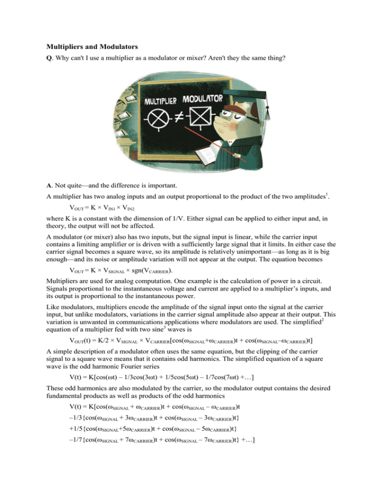
Q. Why can't I use a multiplier as a modulator or mixer? Aren't they the same thing?
A. Not quite—and the difference is important.
A multiplier has two analog inputs and an output proportional to the product of the two amplitudes1.
VOUT = K × VIN1 × VIN2
where K is a constant with the dimension of 1/V. Either signal can be applied to either input and, in
theory, the output will not be affected.
A modulator (or mixer) also has two inputs, but the signal input is linear, while the carrier input
contains a limiting amplifier or is driven with a sufficiently large signal that it limits. In either case the
carrier signal becomes a square wave, so its amplitude is relatively unimportant—as long as it is big
enough—and its noise or amplitude variation will not appear at the output. The equation becomes
VOUT = K × VSIGNAL × sgn(VCARRIER).
Multipliers are used for analog computation. One example is the calculation of power in a circuit.
Signals proportional to the instantaneous voltage and current are applied to a multiplier’s inputs, and
its output is proportional to the instantaneous power.
Like modulators, multipliers encode the amplitude of the signal input onto the signal at the carrier
input, but unlike modulators, variations in the carrier signal amplitude also appear at their output. This
variation is unwanted in communications applications where modulators are used. The simplified2
equation of a multiplier fed with two sine3 waves is
VOUT(t) = K/2 × VSIGNAL × VCARRIER[cos(ωSIGNAL+ωCARRIER)t + cos(ωSIGNAL–ωCARRIER)t]
A simple description of a modulator often uses the same equation, but the clipping of the carrier
signal to a square wave means that it contains odd harmonics. The simplified equation of a square
wave is the odd harmonic Fourier series
V(t) = K[cos(ωt) – 1/3cos(3ωt) + 1/5cos(5ωt) – 1/7cos(7ωt) +…]
These odd harmonics are also modulated by the carrier, so the modulator output contains the desired
fundamental products as well as products of the odd harmonics
V(t) = K[cos(ωSIGNAL + ωCARRIER)t + cos(ωSIGNAL – ωCARRIER)t
–1/3{cos(ωSIGNAL + 3ωCARRIER)t + cos(ωSIGNAL – 3ωCARRIER)t}
+1/5{cos(ωSIGNAL+5ωCARRIER)t + cos(ωSIGNAL – 5ωCARRIER)t}
–1/7{cos(ωSIGNAL + 7ωCARRIER)t + cos(ωSIGNAL – 7ωCARRIER)t} +…]
In many applications, these harmonic products are filtered and ignored, but a correct description of the
modulator function must include them. Sometimes they are useful, and sometimes they overlap the
fundamental products and cause unexpected results.
So before choosing a multiplier, modulator, or mixer, consider what you want to do, and which one
will introduce the least error.
References
Analog Dialogue
Gilbert, Barrie, Considering Multipliers (part 1), Analog Dialogue, Volume 42, Number 4, 2008
Brandon, David, Multichannel DDS Enables Phase-Coherent FSK Modulation, Analog Dialogue,
Volume 44, Number 4, 2010
Product Pages
Mixers/Multipliers
Multipliers/Dividers
Modulators/Demodulators
Tutorials
MT-079: Analog Multipliers
MT-080: Mixers and Modulators
1
The inputs and outputs may be voltages or currents depending on the device. This example uses voltages.
Input and output amplitudes are normalized for simplicity.
3
The equations use cosines as they are easier to manipulate. The final results are the same.
2


