Exam for TDTS 01 Computer Aided Design of Electronics, 2013-06-04
advertisement
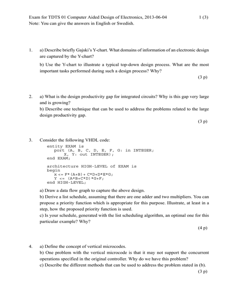
Exam for TDTS 01 Computer Aided Design of Electronics, 2013-06-04 Note: You can give the answers in English or Swedish. 1. 1 (3) a) Describe briefly Gajski’s Y-chart. What domains of information of an electronic design are captured by the Y-chart? b) Use the Y-chart to illustrate a typical top-down design process. What are the most important tasks performed during such a design process? Why? (3 p) 2. a) What is the design productivity gap for integrated circuits? Why is this gap very large and is growing? b) Describe one technique that can be used to address the problems related to the large design productivity gap. (3 p) 3. Consider the following VHDL code: entity EXAM is port (A, B, C, D, E, F, G: in INTEGER; X, Y: out INTEGER); end EXAM; architecture HIGH-LEVEL of EXAM is begin x <= F*(A+B)+ C*D+D*E*G; Y <= (A*B+C*D)*G+F; end HIGH-LEVEL; a) Draw a data flow graph to capture the above design. b) Derive a list schedule, assuming that there are one adder and two multipliers. You can propose a priority function which is appropriate for this purpose. Illustrate, at least in a step, how the proposed priority function is used. c) Is your schedule, generated with the list scheduling algorithm, an optimal one for this particular example? Why? (4 p) 4. a) Define the concept of vertical microcodes. b) One problem with the vertical microcode is that it may not support the concurrent operations specified in the original controller. Why do we have this problem? c) Describe the different methods that can be used to address the problem stated in (b). (3 p) Exam for TDTS 01 Computer Aided Design of Electronics, 2013-06-04 Note: You can give the answers in English or Swedish. 2 (3) 5. a) What is a heuristic algorithm? What are the motivations of using such an algorithm? b) Describe the basic principles of the Genetic algorithms. c) Describe the three genetic operators that are used to generate new solutions in the next generation. Illustrate the operators with simple examples. (4 p) 6. a) What is the Branch-and-Bound technique? Describe the main features of this technique. b) Illustrate the Branch-and-Bound technique with an example. (3 p) 7. a) Why is it difficult to test modern chip which is implemented with mixed technologies? b) Describe one technique which can be used to deal with testing of mixed technologies efficiently. (3 p) 8. a) What is the basic principle of the scan technique? b) What are the main advantages of using the full scan method? c) Discuss the different overheads which are associated with the scan technique. (3 p) The VHDL Part: 9. The VHDL simulation cycle. a) Describe the successive steps of the cycle. b) What do we call a delta cycle? When does such a cycle appear? (3 p) 10. The generate statement. When is it useful? Give an example showing the efficiency of using the generate statement. (2 p) 11. We have discussed the following design units a VHDL model is composed of: entity declaration, architecture body, and configuration declaration. Explain which aspect of the model (or of a part of the model) does each of them capture. (What information regarding the model and its simulation do they carry?) Illustrate by an example for each of them, considering a very simple circuit. (3 p) Exam for TDTS 01 Computer Aided Design of Electronics, 2013-06-04 Note: You can give the answers in English or Swedish. 12. 3 (3) Consider that we are at simulation time 100ns and the driver of a signal S has the following content: 0 10 25 100 ns 115 ns 155 ns The following two signal assignments are performed, one after the other, at the current simulation time of 100ns: S <= 18 after 20 ns, 2 after 45 ns, 5 after 65 ns, 10 after 110 ns, 25 after 135 ns; S <= reject 40 ns inertial 5 after 80 ns; Indicate the content of the driver for signal S a) after the first signal assignment above; b) after the second signal assignment above. (3 p) 13. Consider the signal X having the waveform as follows: X 1 0 10 20 30 50 70 75 85 90 110 130 140 148 t=0 ns Draw the output waveform (Z) if X is applied at the input of a buffer element specified as: a) Z <= transport X after 15 ns b) Z <= X after 15 ns c) Z <= reject 7 ns inertial X after 25 ns (3 p)
