Document 12970173
advertisement
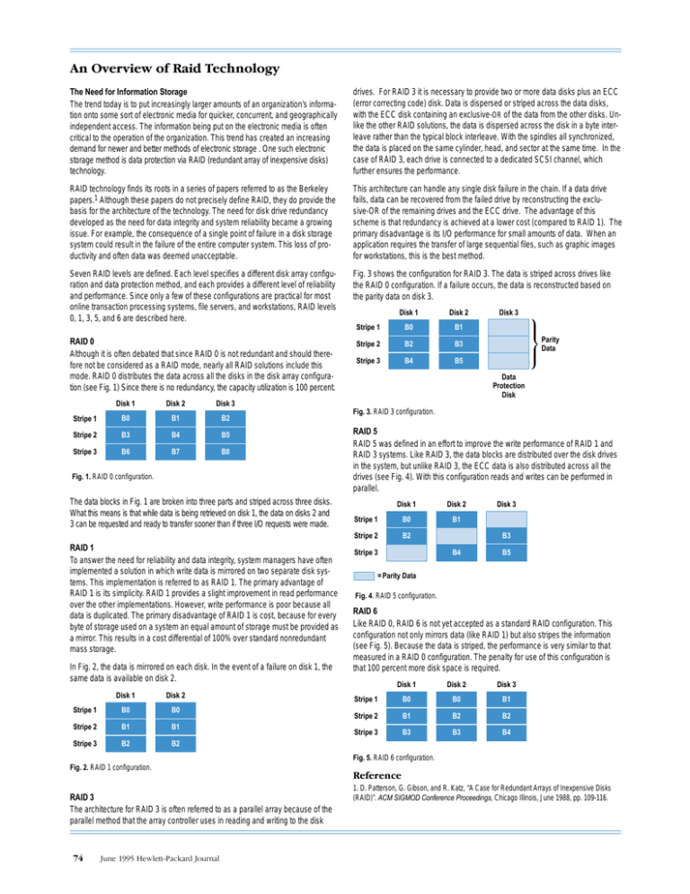
The Need for Information Storage The trend today is to put increasingly larger amounts of an organization’s information onto some sort of electronic media for quicker, concurrent, and geographically independent access. The information being put on the electronic media is often critical to the operation of the organization. This trend has created an increasing demand for newer and better methods of electronic storage . One such electronic storage method is data protection via RAID (redundant array of inexpensive disks) technology. drives. For RAID 3 it is necessary to provide two or more data disks plus an ECC (error correcting code) disk. Data is dispersed or striped across the data disks, with the ECC disk containing an exclusive-OR of the data from the other disks. Unlike the other RAID solutions, the data is dispersed across the disk in a byte interleave rather than the typical block interleave. With the spindles all synchronized, the data is placed on the same cylinder, head, and sector at the same time. In the case of RAID 3, each drive is connected to a dedicated SCSI channel, which further ensures the performance. RAID technology finds its roots in a series of papers referred to as the Berkeley papers.1 Although these papers do not precisely define RAID, they do provide the basis for the architecture of the technology. The need for disk drive redundancy developed as the need for data integrity and system reliability became a growing issue. For example, the consequence of a single point of failure in a disk storage system could result in the failure of the entire computer system. This loss of productivity and often data was deemed unacceptable. This architecture can handle any single disk failure in the chain. If a data drive fails, data can be recovered from the failed drive by reconstructing the exclusive-OR of the remaining drives and the ECC drive. The advantage of this scheme is that redundancy is achieved at a lower cost (compared to RAID 1). The primary disadvantage is its I/O performance for small amounts of data. When an application requires the transfer of large sequential files, such as graphic images for workstations, this is the best method. Seven RAID levels are defined. Each level specifies a different disk array configuration and data protection method, and each provides a different level of reliability and performance. Since only a few of these configurations are practical for most online transaction processing systems, file servers, and workstations, RAID levels 0, 1, 3, 5, and 6 are described here. Fig. 3 shows the configuration for RAID 3. The data is striped across drives like the RAID 0 configuration. If a failure occurs, the data is reconstructed based on the parity data on disk 3. RAID 0 Although it is often debated that since RAID 0 is not redundant and should therefore not be considered as a RAID mode, nearly all RAID solutions include this mode. RAID 0 distributes the data across all the disks in the disk array configuration (see Fig. 1) Since there is no redundancy, the capacity utilization is 100 percent. Disk 1 Disk 2 Disk 3 Stripe 1 B0 B1 B2 Stripe 2 B3 B4 B5 Stripe 3 B6 B7 B8 Fig. 1. RAID 0 configuration. The data blocks in Fig. 1 are broken into three parts and striped across three disks. What this means is that while data is being retrieved on disk 1, the data on disks 2 and 3 can be requested and ready to transfer sooner than if three I/O requests were made. RAID 1 To answer the need for reliability and data integrity, system managers have often implemented a solution in which write data is mirrored on two separate disk systems. This implementation is referred to as RAID 1. The primary advantage of RAID 1 is its simplicity. RAID 1 provides a slight improvement in read performance over the other implementations. However, write performance is poor because all data is duplicated. The primary disadvantage of RAID 1 is cost, because for every byte of storage used on a system an equal amount of storage must be provided as a mirror. This results in a cost differential of 100% over standard nonredundant mass storage. In Fig. 2, the data is mirrored on each disk. In the event of a failure on disk 1, the same data is available on disk 2. Disk 1 Disk 2 Stripe 1 B0 B0 Stripe 2 B1 B1 Stripe 3 B2 B2 Disk 1 Disk 2 Stripe 1 B0 B1 Stripe 2 B2 B3 Stripe 3 B4 B5 Disk 3 Parity Data Data Protection Disk Fig. 3. RAID 3 configuration. RAID 5 RAID 5 was defined in an effort to improve the write performance of RAID 1 and RAID 3 systems. Like RAID 3, the data blocks are distributed over the disk drives in the system, but unlike RAID 3, the ECC data is also distributed across all the drives (see Fig. 4). With this configuration reads and writes can be performed in parallel. Disk 1 Disk 2 Stripe 1 B0 B1 Stripe 2 B2 B3 B4 Stripe 3 Disk 3 B5 = Parity Data Fig. 4. RAID 5 configuration. RAID 6 Like RAID 0, RAID 6 is not yet accepted as a standard RAID configuration. This configuration not only mirrors data (like RAID 1) but also stripes the information (see Fig. 5). Because the data is striped, the performance is very similar to that measured in a RAID 0 configuration. The penalty for use of this configuration is that 100 percent more disk space is required. Disk 1 Disk 2 Disk 3 Stripe 1 B0 B0 B1 Stripe 2 B1 B2 B2 Stripe 3 B3 B3 B4 Fig. 5. RAID 6 configuration. Fig. 2. RAID 1 configuration. RAID 3 The architecture for RAID 3 is often referred to as a parallel array because of the parallel method that the array controller uses in reading and writing to the disk 1. D. Patterson, G. Gibson, and R. Katz, “A Case for Redundant Arrays of Inexpensive Disks (RAID)”. ACM SIGMOD Conference Proceedings, Chicago Illinois, June 1988, pp. 109-116.

