Flyback Charger Circuit
advertisement
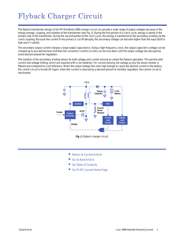
Flyback Charger Circuit The flyback transformer design of the HP OmniBook 5000 charger circuit can provide a wide range of output voltages because of the energy storage, coupling, and isolation of the transformer (see Fig. 1). During the first portion of a clock cycle, energy is stored in the primary side of the transformer. During the second portion of the clock cycle, the energy is transferred to the secondary winding via the core’s coupling. Because the current in the primary is cut off abruptly, the secondary voltage can become higher than the input (dI/dt is high and V = LdI/dt). The secondary output current charges a large output capacitance. Using a high-frequency clock, the output capacitor’s voltage can be charged up to any desired level and then the converter’s control circuitry can be shut down until the output voltage has decayed by some desired amount for regulation. The isolation of the secondary winding allows for both voltage and current sensing to control the flyback operation. This permits both current and voltage limiting, which are required with Li-Ion batteries. For current sensing, the voltage across the sense resistor is filtered and compared to a set reference. When the output voltage has risen high enough to cause the desired current in the battery, the control circuit is turned off. Again, when the current is reduced by a desired amount to maintain regulation, the control circuit is reactivated. +12 V Li-Ion Battery Output Capacitor Snubber Enable N-FET Flyback Controller Filter Current Sense Resistor Disable Current Limit Control Voltage Limit Control Fig. 1. Flyback charger circuit. Subarticle 5a Return to Current Article Go To Next Article Go Table of Contents Go To HP Journal Home Page June 1996 Hewlett-Packard Journal 1
