JOURNAL HEWLETT-PACKARD
advertisement
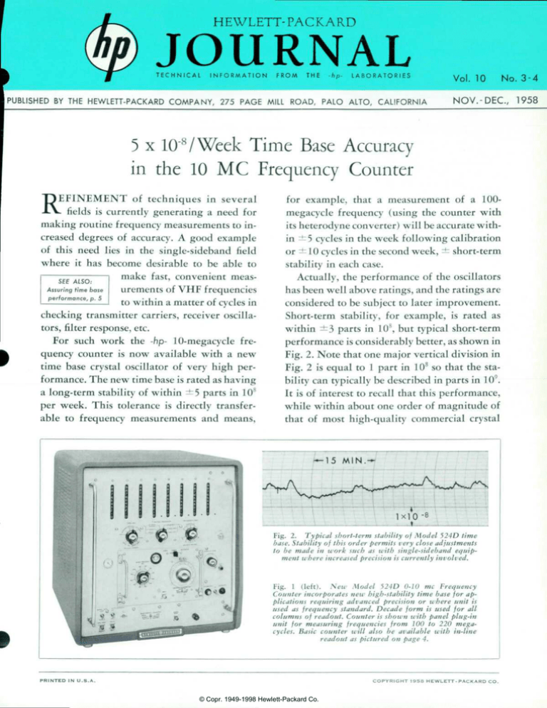
HEWLETT-PACKARD JOURNAL T E C H N I C A L I N F O R M A T I O N F R O M T H E - h p - L A B O R A T O R I E S Vol. 10 No. 3-4 PUBLISHED BY THE HEWLETT-PACKARD COMPANY, 275 PAGE MILL ROAD, PALO ALTO, CALIFORNIA NOV. -DEC., 1958 5 x 10'VWeek Time Base Accuracy in the 10 MC Frequency Counter REFINEMENT of techniques in several fields is currently generating a need for making routine frequency measurements to in creased degrees of accuracy. A good example of this need lies in the single-sideband field where it has become desirable to be able to make fast, convenient meas urements of VHP frequencies to within a matter of cycles in checking transmitter carriers, receiver oscilla tors, filter response, etc. For such work the -hp- 10-megacycle fre quency counter is now available with a new time base crystal oscillator of very high per formance. The new time base is rated as having a long-term stability of within ±5 parts in 108 per week. This tolerance is directly transfer able to frequency measurements and means, for example, that a measurement of a 100megacycle frequency (using the counter with its heterodyne converter) will be accurate with in ± 5 cycles in the week following calibration or ±10 cycles in the second week, ± short-term stability in each case. Actually, the performance of the oscillators has been well above ratings, and the ratings are considered to be subject to later improvement. Short-term stability, for example, is rated as within ±3 parts in 108, but typical short-term performance is considerably better, as shown in Fig. 2. Note that one major vertical division in Fig. 2 is equal to 1 part in 108 so that the sta bility can typically be described in parts in 109. It is of interest to recall that this performance, while within about one order of magnitude of that of most high-quality commercial crystal L. 1 5 MIN.— lxlO-8 - t Fig. 2. Typical short-term stability of Model 524D time base. Stability of this order permits very close adjustments to be made in work such as with single-sideband equip ment where increased precision is currently involved. Fig. 1 (left). New Model 524D 0-10 me Frequency Counter incorporates new high-stability time base for ap plications requiring advanced precision or where unit is used as frequency standard. Decade form is used for all columns of readout. Counter is shown with panel plug-in unit for measuring frequencies from 100 to 220 mega cycles. Basic counter will also be available with in-line readout as pictured on page 4. P R I N T E D I N U . S . A . C O P Y R I G H T © Copr. 1949-1998 Hewlett-Packard Co. 1 9 5 8 H E W L E T T - P A C K A R D C O . #lj#2 #3 #4 #5 #6 #7 #8 #9 1x10⁻⁸ —15 MIN. standards, is supplied within the economic limitations necessary for one circuit of a complete frequencymeasuring instrument whose total selling price is well below that of such commercial standards alone. Space limitations make it imprac tical to present extensive recorded data on long-term stability, but in typical cases the crystals show aging rates of a few parts in 109 per week after the initial stabilization period that crystals normally exhibit has passed. Fig. 3 shows sections spaced a week apart from a long-term sta bility record to illustrate typical sta bility over a one-week period. It can be seen that the aging rate is less than 1 part in 108 for the week. At the -hp- plant, in fact, the equip ments are not released until the crys tals have shown an aging rate of not more than 2.5 parts in 10s per week for a 2-week period. This rate nor mally continues to improve, as in dicated in Fig. 3. Fig. 4. Record of frequency change in Model 524D time base oscillator resulting from 8 different oscillator tube re placements. Large spikes are where recorder went offscale as tubes u'ere removed and new tube warmed. TUBE REPLACEMENT A question that often arises in re gard to stable oscillators concerns the amount of frequency shift that occurs when a tube is changed. This is a factor that is more under the control of the designer than is often realized, and in this oscillator it is one of the factors that has been care fully controlled. Fig. 4 shows typi cal performance in this respect. Eight replacement tubes were in stalled and allowed to operate for several minutes each. Overall effect among all nine tubes was less than 1 part in 10s. Tube-to-tube changes, in fact, were less than 3 parts in 109 in all but one case. Somewhat related data are shown in Fig. 5. This curve demonstrates the effect of discrete changes in capacitance at three points in the oscillator circuit. Information of this nature is used to establish ap proximate coefficients of frequency change to evaluate design factors. Fig. 5. Record of frequency change re sulting from placing lumped capacitance of 10 mmf at grid, plate and output of oscillator to investigate effect on oscil lator of very small changes in circuit capacities. The first upward step in the curve shows the frequency shift caused by placing a lumped capacity of 10 mmf directly across the grid of the oscillator. A frequency change of about 6 parts in 10s or a coefficient of 0.6 parts in 108 per mmf resulted. This information is both a guide to tube replacement changes as well as a measure of the effect of possible slight changes in circuit capacity owing to slight shifts in wiring, etc., that might occur in transporting the instrument. Such shifts probably cannot exceed a few tenths of a micro-microfarad so that resulting '.. (b) Fig. record 524D taken a week apart from long-term stability record of typical Model 524D time base. Low time-base oscillator aging rate minimizes need for calibration checks. © Copr. 1949-1998 Hewlett-Packard Co. — 115VFig. time-base stability. effect of large line-voltage variations on time-base oscillator stability. — 15 MINr- 1X1Q-8 M"URN-ON Fig. time previous over-night standby, a feu'-minute warmup returns time base to its previous frequency and stability. shifts in frequency should be less than 2 parts in 109. The next two smaller steps in Fig. 5 show the effect of a 10 mmf in crease in capacitance at the oscilla tor plate and at the oscillator out put. Additional buffering is used be tween the oscillator output and the point where the signal is extracted, and a 10 mmf increase at this point causes no detectable change in fre quency. TYPICAL USAGE SITUATIONS The frequency counter is rated for operation from power line voltages within the range from 103.5 to 126.5 volts. Within this range line volt age level has very little effect on time base stability. This is demon strated in Fig. 6 which shows the effect of very severe steps in line voltage— actually somewhat beyond ratings. The only noticeable fre quency change occurred when line voltage was changed from 102 volts to 128 volts, i.e., a positive step of 25%. Two other situations about which performance data are of value to the user concern standby operation and initial turn-on characteristics. The instrument is provided with a stand by power switching arrangement such that crystal oven temperature is maintained as long as the instru ment remains connected to a power source. Fig. 7 shows turn-on charac teristics from standby operation after the instrument proper has been turned off for an overnight interval. A few minutes' warmup in this con -15 MIN.— dition is adequate for accurate measurements. Standby operation is also essen tially free of the permanent or semi permanent shifts sometimes ex hibited by crystal oscillators. This is demonstrated in Fig. 8, which shows the stability during three switchings to standby and back. When the instrument has been completely disconnected from pow er for a significant time such that the crystal has cooled to room tem perature, the cooling and subse quent re-heating of the crystal often causes it, in common with any quartz crystal, to undergo a new but accelerated aging cycle which, in effect, may cause a small, permanent shift in the crystal frequency. It is not practical to place ratings on ixicr T •2 HOUR STANDBY : !/2 HOUR' STANDBY 10 MM STANDBY Fig. sometimes when oper standby feature is free of shifts in frequency sometimes encountered when crystal oscillators are thus oper ated, as indicated by three switchings to standby and back in above record. © Copr. 1949-1998 Hewlett-Packard Co. Fig. base will complete cool-off of instrument and crystal, time base oscillator will typically follow a warm-up characteristic as indicated above. — 1 HOUR — 1x10⁻⁸ these effects, but they are usually relatively small. In any case, where highest precision is sought, it is de sirable to make use of the standby feature and to minimize complete turn-offs. Short-time turn-offs, of course, such as might be caused by short power failures or moving the instrument a limited distance, do not appreciably alter the crystal temperature and thus cause no noticeable effect. When the instrument has been cooled to room temperature, it can be expected to follow an initial pat tern similar to that shown in Fig. 9. It is rather usual that the frequency will return to within a few parts in 10s of its previous value within a few hours, but the previous stability may not be reached for several days. AMBIENT TEMPERATURE EFFECTS CHAMBER SET FOR - 2 0  ° C / -20°C REACHED CHAMBER SET FOR + 50°C CHAMBER SET FOR + 25°C +50°C REACHED +25°C REACHED Fig. frequency Record of time-base oscillator stability as complete frequency counter was temperature-cycled in chamber which reached —20° and +50°C. NEW READOUT FEATURES IN THE NEW COUNTER The-hp- ÃO-megocyc/e coun ter with the advanced time base described in the accom panying article has the model number 524D. In addition to its new time base this instru ment also has a full 8-decade readout as shown on fronf page. In other respects, the instrument is the same as the welt-known Model S24B. The new time-base counter will a/so be available in the late spring with an in-line readout using glow-indicator tubes (left) for applications where this type of readout is preferred. The in-line readout instrument has the model number 524C. -hp- instruments are rated for operation over normal room tem peratures, but -hp- policy has al ways been to design for consider ably wider temperature ranges as a safety factor, and instruments are normally "type-tested" in this and other respects over wider than rated ranges. Fig. 10 is a record of time base frequency stability during a temperature test in which the am bient temperature was varied to -20°C and to +50°C as a check on the adequacy of the oven design as well as a check on the remainder of the frequency counter. During this test the time base changed less than 2 parts in 10s, while the complete in strument operated properly. GENERAL The -hp- 10-megacycle frequency counter using the new time base dedescribed above can be seen to pro vide a very high level of accuracy, making the instrument suited to use in laboratory measurements as well as exacting production measure ments. The instrument can also serve in the dual role of a laboratory standard frequency generator, since it provides an output (at 100 kc) (Concluded on page 6) © Copr. 1949-1998 Hewlett-Packard Co. ASSURING TIME BASE PERFORMANCE T T IS OFTEN of special interest to engineers visiting the -hp- plant to observe the procedures used to ascertain the accuracy and stability of precision time base oscillator cir cuits—particularly those that achieve stabilities of within a few parts in 108 such as the Model 524D time base discussed previously in this is sue. By way of illustration, it can be noted that an accuracy of 5 parts in 108 (the rating of the Model 524D) corresponds to knowing the distance between a point in New York City and a point in London to an overall accuracy of within about 1 foot. Ob viously, precision of this order re quires extensive and very careful procedures on the part of an instru ment manufacturer. Since the stability of the time base in the Model 524D is rated in terms of a week, it is necessary in proving these time bases to conduct sufficient tests to assure that ratings will be met over a week's time when the instrument is in service. Because the heart of the time base is a quartz plate and because newly-cut-andprocessed plates usually have not as sumed their final character, such as surance means that tests must be conducted over a several-to-many week period on each plate and that test results must be significantly bet ter than ratings, as dictated by good engineering practice. TEST PROCEDURES As supplied by a crystal processor, quality quartz plates are usually rated as to their equivalent electrical units— inductance, Q (activity), reso nating capacitance, etc. They may also be rated as to aging, based on the methods and care that the proces sor uses. The operation of a plate in a circuit, however, as well as the quality of performance the plate ex hibits during and after its break-in period must be determined. At -hp- the testing of high-preci sion quartz plates is carried out in three main steps. Newly-received Daily measurements of crystal frequency are made and recorded while plate is continuously operated in test stands for several-week period. Before aging, crystal temperature characteristic is plotted with automatic set-up (fore ground) and proper oven temperature determined. plates are connected into special test instruments that first measure their Q and electrical values as a preliminary test of general accept ability. The operating temperature of a plate is then continuously in creased from room temperature to insure that the plate Q does not ex hibit any irregularities or any se vere decreases up to the temperature at which it will be operated. This procedure insures that the plate characteristics do not change in such a way as to cause the oscillator to stop oscillating during some portion of a future warm-up. The second step is a detailed ex amination of the temperature char acteristic of the plate. While operat ing in a test circuit, the plate is heated to a high but safe tempera ture and allowed to cool at a slow rate which previous experience has shown to be satisfactory. During the cooling period the frequency change of the crystal is automatically plot ted against temperature in order to determine its temperature coeffici 5 © Copr. 1949-1998 Hewlett-Packard Co. ent characteristic as well as its zerocoefficient temperature at which the plate will eventually be operated. At the same time the operation of the plate is carefully observed to in sure that no coupling to unwanted vibrational modes exists and that no mechanical instability exists in its mounting. At this point a full set of data ex ists on the plate as to its characteris tics, the change of these character istics with temperature, and the mechanical suitability of the mount ed plate. It remains to determine that the plate is stable over long in tervals. To accomplish this, the plate is installed in its final oven which has been pre-adjusted to oper ate at the zero-coefficient tempera ture determined from the earlier tests. The oven is then inserted in special test stands wherein the plate is operated at its rated frequency (1 megacycle in the case of the Model 524D). The test stand continuously operates the plate and includes (Concluded on page 6) TIME BASE CHECKING 12- 10- 2- to TEMPERATURE °C Typical crystal temperature characteristic automatically plotted with equipment shown on page 5. 10 MC COUNTER (Continued from page 4) from its time base. The aging rate of the new time base is sufficiently low that calibration need be done only infrequently, probably less than once a month, for the instru ment to retain very high accuracy. SPECIFICATIONS -hp- MODEL 524D ELECTRONIC COUNTER (Basic Unit for Frequency Measure ments from 0 cps to 10.1 me) FREQUENCY MEASUREMENT (without plug-in units) Range: 10 cps to 10.1 me. Gafe Time: 0.001, 0.01, 0.1, 1, 10 seconds or manual control. Accuracy: ±1 count ± 0.000 005%. Reads In: Kilocycles; decimal point automati cally positioned. PERIOD MEASUREMENT (without plug-in units) Range: 0 cps to 10 ke. Gafe Time: 1 or 10 cycles of unknown. Accuracy: ±0.3% (measurement one period). ±0.03% (ten period average). Standard Frequency Counted: 10 cps, 1 kc, 100 kc, or 10 me; or externally applied frequency. Reads in: Seconds, milliseconds, or microsec onds; decimal point automatically positioned. GENERAL Registration: 8 places (99,999,999 maximum counts). high -precision frequency -measuring equipment so that the day-to-day changes in the vibrating frequency can be deter mined. Typically, for "good" plates of the type used in the Model 524D, a daily change in frequency of about 1 part in 108 will occur in the earlier part of the run-in period. In plates of this quality these day-to-day changes are usually at tributed to changes in the lattice structure and will normally occur in the same di rection and thus be additive. As the plate continues to operate, the day-to-day changes become smaller and usually taper off into changes that are only a few parts in lO9. When a plate has stabilized such that it operates within 2.5 parts in 108 per week for a two-week period, it is consid ered to have aged satisfactorily and is released for production instruments, pro vided its history during the stabilization period is entirely free of any erratic per formance. Some plates, for example, may show a sudden, discrete shift in frequency and these are not released, at least until a much longer testing period has shown them to be satisfactory. PRODUCTION CHECKS When the crystal in its oven is now in stalled in a production counter, it is al At the same time the new time base is provided in an instrument that is the industry's first and most proved high-speed frequency counter. Com bined with its heterodyne convert ers, it can be used to measure fre quencies up to 220 megacycles. It can also be used with the -hp- trans Stability: Short term: ±3 parts in 10"; long term: -±5 parts in lO1* per week; may be standardized against WWV or used with ex ternal 100 kc or 1 me primary standard. Display Time: Variable 0.1 to 10 seconds but not less than gate time. Display can be held indefinitely. Output Frequencies: Secondary standard fre quencies available at front panel: 10 cps, 1 kc rectangular; 100 kc positive pulse; 10 me sine wave. (Stability as above.) Self Check: Panel control provides automatic count of internal standard 100 kc and 10 me frequencies to assure accuracy of gate and proper operation of counter. Input Voltage: 1 volt rms minimum/1.5 volt peak. Rise time .2 sec (max.). Input Impedance: Approximately 1 megohm, 40 ¿¿/¿f shunt capacitance. External Standard: 100 kc or 1 me signal from external primary standard can be applied to unit for highest accuracy. 2 volts rms re quired. Nominal input impedance: 1 meg ohm, 40 /¿Mà shunt. Connectors: BNC Type. Power Supply: 115/230 volts ±10%, 50-60 cps, approximately 600 watts. Dimensions: Cabinet Mount: 20" wide, 21 W high, 23'/2" deep overall. Rack Mount: 19" wide, 191/4" high, 22V2" deep behind panel. Weight: Cabinet Mount: Net 118 Ibs., Shipping 168 Ibs. Rack Mount: Net 108 Ibs., Shipping 172 Ibs. © Copr. 1949-1998 Hewlett-Packard Co. lowed to fully reach its oven temperature and then adjusted to be within 1 part in 10* of its f, value in the new circuit. The complete frequency counter is then con nected to a power-cycling device which applies power to the instrument for alternate half-hour periods for 4 days. The instrument is thus turned on some 96 times and turned off a like number of times. This test is designed as an overall check on the complete instrument as well as the crystal oscillator. At the end of this period the oscillator frequency is again measured and adjusted to be within a few parts in 109. From this time on during the remain der of testing that the instrument under goes the oscillator must remain within 2 parts in 108 in order to be released at final test. It can be seen from the foregoing that -hp- time bases are put through extremely rigorous tests indeed to insure that ratings can be depended on in field use. Further, since quartz plates that are free of imper fections and properly operated circuitwise have a broad history of improving with time, their performance can, in gen eral, be expected to improve with time up to the limits set by the oven itself. fer oscillator to measure up to 12 kilomegacycles. At the other ex treme the counter can be used with its period multiplier unit to meas ure the average period of low fre quencies to high accuracy. —LaThare N. Bodily and Leonard S. Cutler Accessories Furnisfiwf: -hp- AC-16K Cable As sembly, 48" RG-58/U cable, terminated each end with UG-88/U BNC male Connectors. Plun-in Units: -hp- 525A Frequency Converter, 10 cps to 100 me. $250.00. -hp- 525B Frequency Converter, 100 me to 220 me. $250.00. -hp- 526A Video Amplifier, 10 cps to 10.1 me. $175.00. -hp- 5268 Time Interval Unit, 1 fisec. to 107 sec. $175.00. -hp- 526C Period Multiplier, 0 cps to 10 kc. $225.00. Complementary Equipment: -hp- 540A Transfer Oscillator, Cab:net Mount, $615.00. Rack Mount, $600.00. -hp- Model 440A Detector Mount, $85.00. -hp- 560A Digital Recorder, Cabinet Mount, $1,265.00. Rack Mount, $1,250.00. Accessories Available: Test Cable Set to inter connect -hp- 524 and 525/526 units during test and adjustment of auxiliary units, Soecify -hp- 524B-16P, 16 conductor cable $20.00, and -ho- 52¿B- 16Q, 8 conductor cable $15.00. -hp- 524D-95A, Model 560A Digital Recorder Adopter Kit for field installation, $35.00. Price: -hp- 524D Electronic Counter, Cabinet Mount, $2,150.00. Rack Mount, $2,125.00. For Model 560A Digital Rororder operation, add $75.00, specify C03-524D. Prices f.o.b. Palo Alto, California. Data subject to change without notice.
