Enhancement of Shape Perception by Surface Reflectance Transformation Tom Malzbender *, Dan Gelb
advertisement
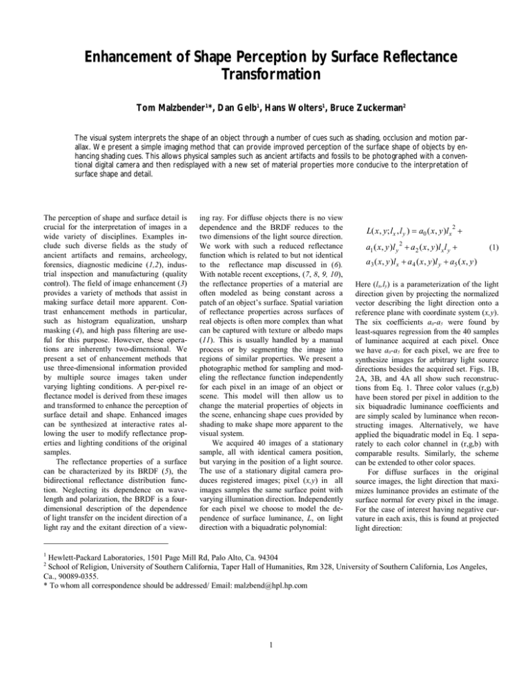
Enhancement of Shape Perception by Surface Reflectance Transformation Tom Malzbender1*, Dan Gelb1, Hans Wolters1, Bruce Zuckerman2 The visual system interprets the shape of an object through a number of cues such as shading, occlusion and motion parallax. We present a simple imaging method that can provide improved perception of the surface shape of objects by enhancing shading cues. This allows physical samples such as ancient artifacts and fossils to be photographed with a conventional digital camera and then redisplayed with a new set of material properties more conducive to the interpretation of surface shape and detail. The perception of shape and surface detail is crucial for the interpretation of images in a wide variety of disciplines. Examples include such diverse fields as the study of ancient artifacts and remains, archeology, forensics, diagnostic medicine (1,2), industrial inspection and manufacturing (quality control). The field of image enhancement (3) provides a variety of methods that assist in making surface detail more apparent. Contrast enhancement methods in particular, such as histogram equalization, unsharp masking (4), and high pass filtering are useful for this purpose. However, these operations are inherently two-dimensional. We present a set of enhancement methods that use three-dimensional information provided by multiple source images taken under varying lighting conditions. A per-pixel reflectance model is derived from these images and transformed to enhance the perception of surface detail and shape. Enhanced images can be synthesized at interactive rates allowing the user to modify reflectance properties and lighting conditions of the original samples. The reflectance properties of a surface can be characterized by its BRDF (5), the bidirectional reflectance distribution function. Neglecting its dependence on wavelength and polarization, the BRDF is a fourdimensional description of the dependence of light transfer on the incident direction of a light ray and the exitant direction of a view- ing ray. For diffuse objects there is no view dependence and the BRDF reduces to the two dimensions of the light source direction. We work with such a reduced reflectance function which is related to but not identical to the reflectance map discussed in (6). With notable recent exceptions, (7, 8, 9, 10), the reflectance properties of a material are often modeled as being constant across a patch of an object’s surface. Spatial variation of reflectance properties across surfaces of real objects is often more complex than what can be captured with texture or albedo maps (11). This is usually handled by a manual process or by segmenting the image into regions of similar properties. We present a photographic method for sampling and modeling the reflectance function independently for each pixel in an image of an object or scene. This model will then allow us to change the material properties of objects in the scene, enhancing shape cues provided by shading to make shape more apparent to the visual system. We acquired 40 images of a stationary sample, all with identical camera position, but varying in the position of a light source. The use of a stationary digital camera produces registered images; pixel (x,y) in all images samples the same surface point with varying illumination direction. Independently for each pixel we choose to model the dependence of surface luminance, L, on light direction with a biquadratic polynomial: 1 L( x , y; lx , l y ) = a0 ( x , y )l x + 2 a1 ( x, y )l y 2 + a2 ( x , y )l x l y + a3 ( x, y )lx + a4 ( x , y )l y + a5 ( x, y ) Here (lx,ly) is a parameterization of the light direction given by projecting the normalized vector describing the light direction onto a reference plane with coordinate system (x,y). The six coefficients a0-a5 were found by least-squares regression from the 40 samples of luminance acquired at each pixel. Once we have a0-a5 for each pixel, we are free to synthesize images for arbitrary light source directions besides the acquired set. Figs. 1B, 2A, 3B, and 4A all show such reconstructions from Eq. 1. Three color values (r,g,b) have been stored per pixel in addition to the six biquadradic luminance coefficients and are simply scaled by luminance when reconstructing images. Alternatively, we have applied the biquadratic model in Eq. 1 separately to each color channel in (r,g,b) with comparable results. Similarly, the scheme can be extended to other color spaces. For diffuse surfaces in the original source images, the light direction that maximizes luminance provides an estimate of the surface normal for every pixel in the image. For the case of interest having negative curvature in each axis, this is found at projected light direction: Hewlett-Packard Laboratories, 1501 Page Mill Rd, Palo Alto, Ca. 94304 School of Religion, University of Southern California, Taper Hall of Humanities, Rm 328, University of Southern California, Los Angeles, Ca., 90089-0355. * To whom all correspondence should be addressed/ Email: malzbend@hpl.hp.com 2 1 (1) l x0 = l y0 = a2 a4 − 2a1a3 4a0 a1 − a2 2 a 2 a3 − 2a0 a4 4a0 a1 − a2 2 by solving Eq. 1 for (2) (3) ∂L ∂L = = 0 at each ∂x ∂y pixel. The parameterization of the light direction is convenient since lx0,ly0 are two components of our estimated surface normal. The full estimated normal vector is simply: parabola. The gaussian curvature of this parabola (its second spatial derivative) can be increased arbitrarily by a gain factor g by computing new luminance coefficients using the following transformation: a0 ' = ga0 a1 ' = ga1 a2 ' = ga2 a3 ' = (1 − g )(2a0 l x 0 + a2 l yo ) + a3 a4 ' = (1 − g )(2a1l y 0 + a 2l x0 ) + a4 a5 ' = (1 − g )(a0 l x 0 2 + a1l y 0 2 + a2 l x0 l y 0 ) + (a3 − a3 )l x 0 + (a4 − a4 ' )l y 0 + a5 ' v 2 2 N = (l x0 , l y 0 , 1 − l x0 − l y 0 ) (4) Photometric stereo methods from computer vision would provide an alternate approach to this stage of surface normal recovery (9) and would also be affected by the presence of self-shadowing, as is our method. This extracted surface normal can be used in several ways to enhance the appearance of surface shape and detail. We have implemented three methods that exaggerate the reflectance function in various manners. Method 1: Specular enhancement. For every pixel (x,y), the normal vector can be used in a lighting equation to add either diffuse or specular shading effects to the image. Simulation of specularity is particularly effective at enhancing the perception of surface shape (12). To achieve specular effects with the computationally simple and well-known Blinn/Phong (13) model, we use v the halfway vector H (between a simulated light source and viewer) and the estimated r surface normal N , to compute a color contribution to the original image: v v v v I = Ck s ( H ⋅N ) n (5) We are free to change the properties of the surface (specularity ks, specular exponent n) and simulated light source (position, color v C ) under interactive control. Our method is demonstrated in Figs. 1 and 2 on a neoSumerian tablet discussed later in the paper. We have effectively modified the reflectance properties of the tablet to enhance perception of surface shape, making the object more “readable”. Method 2: Diffuse gain. For diffuse objects, the original photographed surfaces typically exhibit a gently varying change in surface intensity across light direction that we have fit with a 2 dimensional convex (6) This keeps the luminance maximum at the same location, namely (lxo,lyo), thereby retaining the surface normal direction. It also maintains the luminance at (lxo,lyo) retaining the surface albedo and color in this direction. However, the directional sensitivity of the surface to light is increased by this transformation, enhancing the reflectance properties of the sample. Fig. 3 shows the method on a funerary statuette called an ushabti from ancient Egypt. Made out of a glazed frit material (faience), its purpose was to carry out work on behalf of the deceased in the netherworld. Note the enhanced definition of the inscription. Method 3: Light direction extrapolation. Light source direction is a normalized quantity encoded by the projected light direction lx,ly. Physically realizable light sources are limited to l x + l y ≤1 since the light di2 2 rection is described by a normalized vector with three real components, as shown in Eq. 4. However, this constraint need not be applied when evaluating Eq. 1, allowing one to extrapolate the reflectance model beyond what is geometrically achievable. This extrapolation does not have an exact physical analog, but it provides lighting that is more oblique than any used in the original source images, providing enhanced contrast. These three enhancement methods may be adaptable to a variety of studies where subtle distinctions in depth are required for interpretation. We have found them useful for reading certain types of ancient inscriptions, Fig. 1 being an example. Depicted is a small tablet written in neo-Sumerian, dating from the 2nd millennium BCE, belonging to the Archaeological Research Collection of the University of Southern California. This tablet has two types of information of concern to the investigator. First there is an endorsement created by a cylinder seal, 2 that is, a small, cylindrically shaped object that has a complicated design incised on its rolling surface. When this is rolled out on wet clay it leaves a raised (bas relief) imprint that functioned as an identification signature for the owner of the seal. In this case the sealing has two components an illustrative scene showing a seated man with a standing figure before him on the left and an imprint in Sumerian cuneiform or “wedge writing” to his right, which records the owner's name and title. The second sort of data are cuneiform wedges pressed or indented into the clay that record a business transaction and are the ancient equivalent of a receipt of trade. Using standard photographic techniques, it is difficult to depict both features in the same image, since the light placement required for getting shadow detail in bas relief is substantially different from that required to show shadow detail for indented wedges. The methods described here provide interactive control of light source position and surface material properties and are helpful with such tradeoffs. A demonstration of these tools and datasets can be downloaded from http://www.hpl.hp.com/ptm. References and Notes 1. For example examining appearance of dermatological lesions and specifying morphologic changes of suspicious cutaneous lesions. 2. B.J.Fox, J Am Acad Dermatol, 12, 597, (1985). 3. J.C.Russ, Image Processing Handbook (CRC Press, Boca Raton, ed. 2, 1995), pp.211-275. 4. W.K.Pratt, Digital Image Processing (Wiley, New York, 1978), pp.322-326. 5. F.E.Nicodemus, J.C.Richmond, J.J.Hsia, (U.S. Dept. of Commerce, National Bureau of Standards, 1977). 6. B.K.P.Horn, Artificial Intelligence 8, 201 (1977) 7. K.J.Dana, B.Ginneken, S.K.Nayar, J.J. Koenderink, A.C.M. T.O.G. 18,1 (1999). 8. Y.Sato, M.D.Wheeler, K.Ikeuchi, Proc. Siggraph 97, 379,(1997). 9. H.Rushmeir, G.Taubin, A. Gueziec, Proc. Eurographics 97, 35, (1997). 10. P.Debevec, Unpublished recent work. 11. Y.Yu, P. Debevec, J. Malik, T. Hawkins, Proc. Siggraph 99, 215,(1999). 12. It is common for designers to use specular reflections to understand shape, in the automotive industry for example. References (14,15) discuss these automotive design methods. 13. A. Watt, 3D Computer Graphics, (AddisonWesley, New York, ed. 2, 1993), p. 100. 14. R.Klass, Comp. Aided Design. 12, 73 (1980). 15. T.Poeschl, Comp. Aided Geometrical Design, 1, 163, (1984). Fig. 1. Specular enhancement from photographs. (A) One of 40 source images, each with varying light source direction. (B) Reconstruction from a biquadratic model of diffuse reflectance per pixel. (C) An image computed by extracting surface normals for each pixel and applying a specular lighting model per pixel. (D) Highlights computed in (C) added to (B). Light direction is the same for all four images and can be updated at interactive rates. Fig. 2. Variation of surface color to light source direction for the same pixel in Fig. 1B,1C and 1D respectively. Specularity can be introduced to enhance surface detail. Fig. 3 Diffuse enhancement from photographs (A) Original source image. (B) R econstruction from a biquadratic reflectance model. (C) Diffuse enhancement a reconstruction that exaggerates the di ffuse reflectance properties by a gain fa ctor (g = 1.9 here), keeping the surface normal estimate constant. These images have identical light directions and intens ities. Fig. 4. Variation of surface color to light source direction for the same pixel in Fig 3B,3C. The diffuse response to light dire ction is increased, but the estimated su rface normal (represented by the crosshair) is unaffected. 3
