Designing and Tuning of PI Controller for Flyback Converter
advertisement

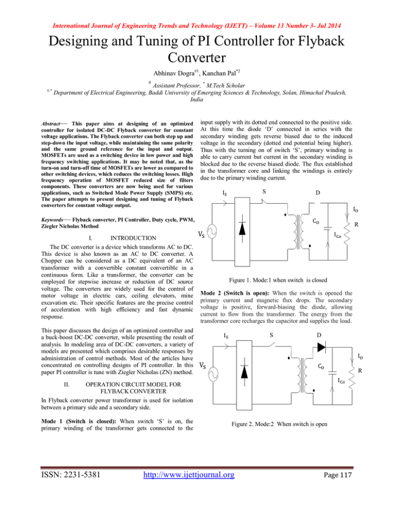
International Journal of Engineering Trends and Technology (IJETT) – Volume 13 Number 3- Jul 2014 Designing and Tuning of PI Controller for Flyback Converter Abhinav Dogra#1, Kanchan Pal*2 # #,* Assistant Professor, * M.Tech Scholar Department of Electrical Engineering, Baddi University of Emerging Sciences & Technology, Solan, Himachal Pradesh, India Abstract— This paper aims at designing of an optimized controller for isolated DC-DC Flyback converter for constant voltage applications. The Flyback converter can both step up and step-down the input voltage, while maintaining the same polarity and the same ground reference for the input and output. MOSFETs are used as a switching device in low power and high frequency switching applications. It may be noted that, as the turn-on and turn-off time of MOSFETs are lower as compared to other switching devices, which reduces the switching losses. High frequency operation of MOSFET reduced size of filters components. These converters are now being used for various applications, such as Switched Mode Power Supply (SMPS) etc. The paper attempts to present designing and tuning of Flyback converters for constant voltage output. input supply with its dotted end connected to the positive side. At this time the diode ‘D’ connected in series with the secondary winding gets reverse biased due to the induced voltage in the secondary (dotted end potential being higher). Thus with the turning on of switch ‘S’, primary winding is able to carry current but current in the secondary winding is blocked due to the reverse biased diode. The flux established in the transformer core and linking the windings is entirely due to the primary winding current. S I D I Keywords— Flyback converter, PI Controller, Duty cycle, PWM, Ziegler Nicholas Method I. INTRODUCTION The DC converter is a device which transforms AC to DC. This device is also known as an AC to DC converter. A Chopper can be considered as a DC equivalent of an AC transformer with a convertible constant convertible in a continuous form. Like a transformer, the converter can be employed for stepwise increase or reduction of DC source voltage. The converters are widely used for the control of motor voltage in electric cars, ceiling elevators, mine excavation etc. Their specific features are the precise control of acceleration with high efficiency and fast dynamic response. This paper discusses the design of an optimized controller and a buck-boost DC-DC converter, while presenting the result of analysis. In modeling area of DC-DC converters, a variety of models are presented which comprises desirable responses by administration of control methods. Most of the articles have concentrated on controlling designs of PI controller. In this paper PI controller is tune with Ziegler Nicholas (ZN) method. C R V I Figure 1. Mode:1 when switch is closed Mode 2 (Switch is open): When the switch is opened the primary current and magnetic flux drops. The secondary voltage is positive, forward-biasing the diode, allowing current to flow from the transformer. The energy from the transformer core recharges the capacitor and supplies the load. I S D I V C R I II. OPERATION CIRCUIT MODEL FOR FLYBACK CONVERTER In Flyback converter power transformer is used for isolation between a primary side and a secondary side. Mode 1 (Switch is closed): When switch ‘S’ is on, the primary winding of the transformer gets connected to the ISSN: 2231-5381 Figure 2. Mode:2 When switch is open http://www.ijettjournal.org Page 117 International Journal of Engineering Trends and Technology (IJETT) – Volume 13 Number 3- Jul 2014 load under steady state conditions, the variation of input voltage shall result in fluctuation in output Therefore, a closed loop controller is required with optimized parameters to suit the constant voltage output as per requirement of load. Pulse Generator m D S i - + g A + B - 1 + v - 2 Scope 2 C. Controller for closed loop flyback converter give design equations: g m D S i - + Figure 3. Simulation model of flyback converter for open loop control A + B - 1 + v - 2 Scope 2 A. Design parameter and equations for flyback converter: V = D(N ⁄N )V /(1 − D) L = DV ⁄(∆I ) f C = V D⁄(f R∆V ) Where f = switching frequency ∆I = peak to peak ripple current I (assuming 10% of I ) ∆V = voltage ripple (assuming 5% of V ) N ⁄N = Transformer turn ratio. Repeating Sequence 400 8 Gain <= Relational Operator T To Workspace1 Figure 5. Simulation model of flyback converter for closed loop control The Simulink Schematic of flyback converter with analog PI controller is shown in figure 5. The output voltage is sensed Vout and compared with the input voltage Vref .An error signal is produced which is processed through PI controller to generate a control voltage. The control voltage is used to feed to the PWM generator for control of switch. The PI controller has two parameters namely KP and KI. 500 450 PI controller has transfer function: C(s) = + Where, =Proportional gain and = Integral gain. 400 V (Volts) Discrete PI Controller Scope 1 Clock B. The calculated value of flyback converter: Input voltage (V ) = 220 volts Output voltage (V ) = 400 volts Duty cycle (D) = 38.18% Switching frequency (f) = 25 kHz Magnetizing inductor (L ) = 37 mH Filter capacitor (C ) = 0.252 µF PI Constant 350 300 250 500 200 100 50 0 0 0.05 0.1 0.15 0.2 0.25 0.3 0.35 0.4 0.45 0.5 400 300 200 100 Time (Secs) Figure 4. Open loop response of flyback converter The results of open loop flyback converter is shown in figure 5, which depicts peak to peak ripple voltage (∆Vo) is 53 Volt and maximum o v e r s h o o t of 1 2 %. Since the design equations assume constant input voltage and constant ISSN: 2231-5381 V (Volts) 150 0 0 0.1 0.2 0.3 0.4 0.5 Time (Secs) Figure. 6 Closed loop response of Output voltage Vs Time http://www.ijettjournal.org Page 118 International Journal of Engineering Trends and Technology (IJETT) – Volume 13 Number 3- Jul 2014 D. Tuning of PI controller by Ziegler-Nicholas Method: Ziegler-Nicholas is one of the oldest methods of tuning of PID controller. Remove integral and derivative action. Set integral time (Ti) to 999 or its largest value and set the derivative controller (Td) to zero. Create a small disturbance in the loop by changing the set point. Adjust the proportional, increasing and/or decreasing, the gain until the oscillations have constant amplitude. Record the gain value (Ku) and period of oscillation (Pu). Closed-Loop Calculations of Kc, Ti, Td 1.4 (Ampere) 1.2 1 0.8 0.6 I 0.4 0.2 0 0 0.05 0.1 0.15 0.2 0.25 0.3 0.35 Time (Secs) Figure 7. Closed loop response of Magnetization current (I ) Vs Time TABLE I P PI PID The results of closed loop flyback converter is shown in fig.7 which has maximum overshoot of 3.82%, settling time 0.01sec and rise time 0.01 sec. III. Kc Ku /2 Ku /2.2 Ku /1.7 Ti Pu/1.2 Pu/2 Td Pu/8 EFFECT DUE TO VARIATION PI CONTROLLER PARAMETERS KP AND KI ON OUTPUT VOLTAGE AND INDUCTOR CURRENT TABLE II. Performance parameters when L =47.60 mH, C = 0.7656 µF, K = 0.019 and value of K is varied. Voltage(V ) K Current (I ) O.S (%) Settling Time Rise Time O.S (%) Settling Time Rise Time 1.3 0.01 0.01 2.3 0.01 0.01 0.000019 0.0001 1.3 0.01 0.01 2.41 0.01 0.01 0.00011 3.82 0.01 0.01 7.62 0.01 0.01 0.00012 18.9 0.0162 0.01 41.42 0.0151 0.01 0.00013 20.5 0.0184 0.01 45.47 0.0177 0.01 0.00014 20.5 0.0186 0.01 47.49 0.0177 0.01 (a) Performance of output voltage (V ) Vs time graph for flyback converter when K value is varied. % Over Shoot V (Volts) 500 400 300 200 100 0 50 40 30 20 10 0 0 0 0.1 0.2 0.3 0.4 6E-05 0.00012 0.00018 K 0.5 Time (Secs) Figure 8. Output voltage Vs time with K = 0.00011 ISSN: 2231-5381 Figure 9. Effect on overshoot due to variation in K http://www.ijettjournal.org Page 119 International Journal of Engineering Trends and Technology (IJETT) – Volume 13 Number 3- Jul 2014 0.015 Rise Time (Secs) Settling Time (Secs) 0.02 0.015 0.01 0.005 0 0 6E-05 0.00012 0.01 0.005 0 0.00018 0 6E-05 K Figure 11. Effect on rise time due to variation in K ) Vs time graph for flyback converter when K value is varied. (b) Performance of magnetization current (I % Over Shoot (Ampere) I 1.4 0.4 1 0.8 0.6 0.2 0 50 40 30 20 10 0 0 0 0.05 0.1 0.15 0.2 0.25 0.3 6E-05 Figure 13. Effect on overshoot due to variation in K ) Vs time with 0.02 0.015 0.01 0.005 0 Rise Time (Secs) Settling Time (secs) 0.00018 K Figure 12. Magnetization current (I K = 0.00011 6E-05 0.00012 0.35 Time (Secs) 0 0.00018 K Figure 10. Effect on settling time due to variation in K 1.2 0.00012 0.00012 0.00018 0.015 0.01 0.005 0 0 6E-05 K 0.00012 0.00018 K Figure 15. Effect on rise time due to variation in K Figure 14. Effect on settling time due to variation in K TABLE III. Performance parameters when L = 47.60 mH, C = 0.7656 µF,K = 0.00011, K value is varied . K Voltage(V ) Current (I ) 0.0016 O.S (%) 1.5 Settling Time 0.01 Rise Time 0.01 O.S (%) 2.76 Settling Time 0.01 Rise Time 0.01 0.0017 1.95 0.01 0.01 3.8 0.01 0.01 0.0018 2.87 0.01 0.01 5.71 0.01 0.01 0.0019 3.82 0.01 0.01 7.62 0.01 0.01 0.002 5 0.01 0.01 10.19 0.0112 0.01 0.0021 6 0.0127 0.01 12.38 0.0121 0.01 ISSN: 2231-5381 http://www.ijettjournal.org Page 120 International Journal of Engineering Trends and Technology (IJETT) – Volume 13 Number 3- Jul 2014 (a) Performance of output voltage (V ) Vs time graph for flyback converter when K value is varied. 500 8 % Over Shoot V (Volts) 400 300 200 6 4 2 100 0 0 0.001 0 0.1 0.2 0.3 0.4 0.015 Rise Time (Secs) Settling Time (Secs) 0.01 0.005 0.002 0.0025 Figure 17. Effect on overshoot due to variation in K 0.015 0.0015 0.002 K Time (Secs) Figure 16. Output voltage Vs time with K = 0.0019 0 0.001 0.0015 0.5 0.01 0.005 0 0.001 0.0025 0.0015 0.002 0.0025 K K Figure 19. Effect on rise time due to variation in K Figure 18. Effect on settling time due to variation in K (b) Performance of magnetization current (I ) Vs time graph for flyback converter when K value is varied. 15 % Over Shoot (Ampere) 1.4 1.2 1 0.8 0.6 I 0.4 0.2 0 0 0.05 0.1 0.15 0.2 0.25 0.3 0.35 Time (Secs) 0 0.001 Rise Time (Secs) 0.01 0.005 0.0015 0.0015 K 0.0025 0.002 0.0025 0.015 0.01 0.005 0 0.001 0.0015 0.002 0.0025 K K Figure 22. Effect on settling time due to variation in K ISSN: 2231-5381 0.002 ) Vs time 0.015 Settling Time (Secs) 5 Figure 21. Effect on overshoot due to variation in K Figure 20. Magnetization current (I with K = 0.0019 0 0.001 10 Figure 23. Effect on rise time due to variation in K http://www.ijettjournal.org Page 121 International Journal of Engineering Trends and Technology (IJETT) – Volume 13 Number 3- Jul 2014 IV. CONCLUSION The designing of flyback converters has been carried out for constant voltage applications considering inductor and capacitor as performance parameters. Flyback converter has been designed to deliver 400 volts DC to a 400 watt load. Performance and applicability of this converter is presented on the basis of simulation in MATLAB SIMULINK. Flyback converters are employed for LOW POWER applications below 150 W and with voltages below 500V. Note that the core with an air gap doubles as a transformer and an output choke— saving one heavy and costly component. Now cut the electrical connection between the two parallel inductors and use only magnetic coupling between the two L’s by purposefully winding them on the same magnetic core. This makes for a two winding inductor--each separately wound and isolated electrically from each other except for the common magnetic core coupling . We now lose the common ground. Current no longer flows simultaneously in the two electrically isolated inductor windings due to the core coupling alone because the primary and the secondary have their own seriesswitches. Moreover, these switches can act in a complementary fashion so that when one is on the other is off. The design concepts are validated through simulation and results obtained show that a closed loop system using flyback converter will be highly stable with high efficiency. Better efficiency due to: moderate duty cycles, lower voltage MOSFETs and rectifiers, and reduced switching losses due to reduced peak-to-peak voltage swing. ISSN: 2231-5381 REFERENCES [1] [2] [3] [4] [5] [6] [7] [8] Sanjeev Singh and Bhim Singh, “An adjustable speed PMBLDCM drive for air conditioner using PFC Zeta converter,” Int. J. Power Electron. (IJPElec), vol. 3, no. 2, pp. 171–188, Apr. 2011. Sanjeev Singh and Bhim Singh, “Power Electronics, Drives and Energy Systems (PEDES),” in Proc. IEEE PEDES’2010. Sanjeev Singh and Bhim Singh, “Single-phase power factor controller topologies for permanent magnet brushless DC motor drives,” in IET Power Electron., 2010, Vol. 3, Iss. 2, pp. 147–175. Sanjeev Singh and Bhim Singh, “A voltage controlled adjustable speed PMBLDCM drive using a single-stage PFC half-bridge converter,” in Proc. IEEE APEC’10, 2010, pp. 1976–1983. Sanjeev Singh and Bhim Singh, “Comprehensive study of singlephase AC-DC power factor corrected converters with highfrequency isolation” IEEE Trans. on Industrial Informatics, vol. 7, no. 4, Nov. 2011, , pp. 540-556. Altamir Ronsani and Ivo Barbi, “Three-phase single stage AC-DC buck-boost converter operating in buck and boost modes” in Proc. IEEE, 2011, pp.176-182. Boopathy.K and Dr.Bhoopathy Bagan .K, “Buck Boost converter with improved transient response for low power applications” in Proc. IEEE SIEA, Sep 2011, pp. 155-160. Marcos Orellana, Stephane Petibon and Bruno Estibals, “Four switch buck-boost converter for photovoltaic DC-DC ower applications” in proc. IEEE, ISGE, 2010, pp.469-474. [9] S. C. Raviraj and P. C. Sen, “Comparative study of proportionalintegral, sliding mode, and flay logic controllers for power converters,” IEEE Transactions on Industrial Applications, vol 33, no.2, pp.518— 524, MariApr. 1997. [10] Sanjeev Singh and Bhim Singh, “Power quality improved PMBLDCM drive for adjustable speed application with reduced sensor buck-boost PFC converter” in proc. IEEE 11th ICETET, 2011, pp.180-184. [11] M. Namnabat, M. Baysti Poodeh, S. Eshlehardiha, “Comparison the Control Methods in Improvement the Performance of the DC-DC Converter”, The 7’ international conference on power electronics, 22- 26, EXCO, Daegu, Korea, 2007. [12] Venkstarsmanan, A. Sabanoivc, and S. Culç “Sliding mode control of dc-to-dc converters,” in Proc. IEEE ConE Industrial Electronics, Control Instnjmentations (IECON), pp. 25 1-258, 1985. http://www.ijettjournal.org Page 122


