Simulation Based Analysis of Two Different Control Strategies for PMSM
advertisement
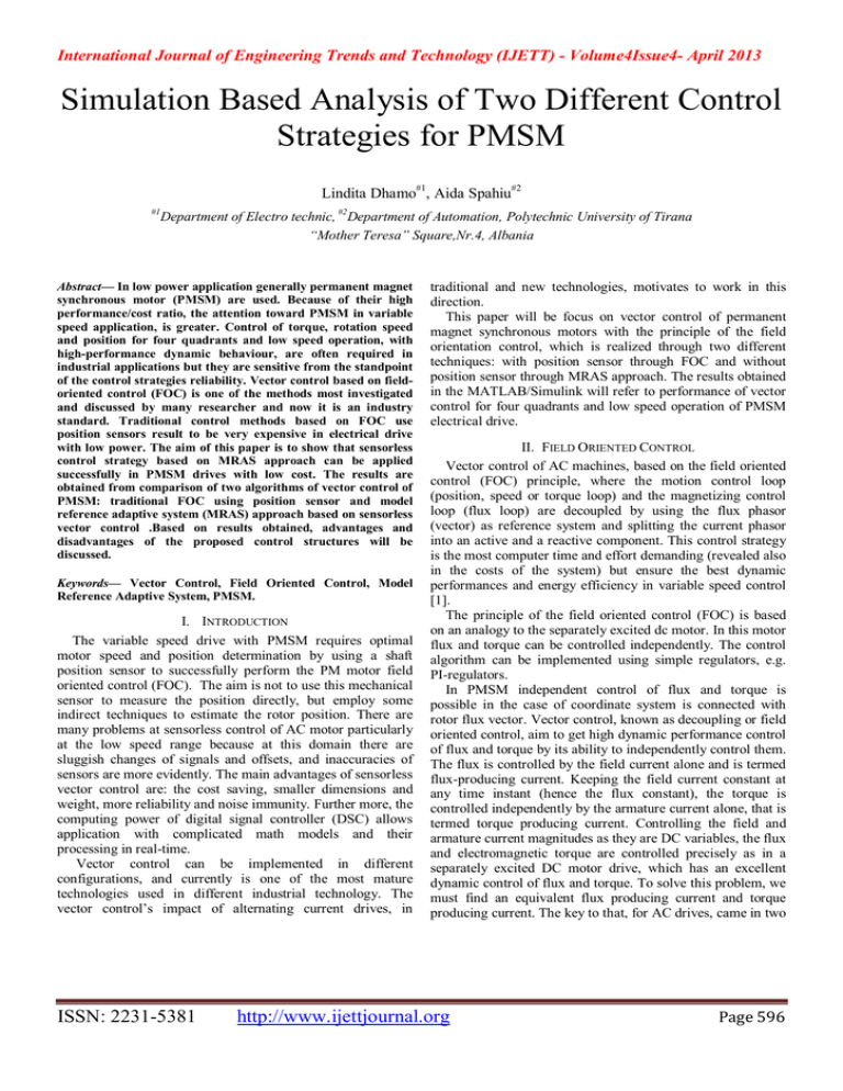
International Journal of Engineering Trends and Technology (IJETT) - Volume4Issue4- April 2013 Simulation Based Analysis of Two Different Control Strategies for PMSM Lindita Dhamo#1, Aida Spahiu#2 #1 Department of Electro technic, #2Department of Automation, Polytechnic University of Tirana “Mother Teresa” Square,Nr.4, Albania Abstract— In low power application generally permanent magnet synchronous motor (PMSM) are used. Because of their high performance/cost ratio, the attention toward PMSM in variable speed application, is greater. Control of torque, rotation speed and position for four quadrants and low speed operation, with high-performance dynamic behaviour, are often required in industrial applications but they are sensitive from the standpoint of the control strategies reliability. Vector control based on fieldoriented control (FOC) is one of the methods most investigated and discussed by many researcher and now it is an industry standard. Traditional control methods based on FOC use position sensors result to be very expensive in electrical drive with low power. The aim of this paper is to show that sensorless control strategy based on MRAS approach can be applied successfully in PMSM drives with low cost. The results are obtained from comparison of two algorithms of vector control of PMSM: traditional FOC using position sensor and model reference adaptive system (MRAS) approach based on sensorless vector control .Based on results obtained, advantages and disadvantages of the proposed control structures will be discussed. Keywords— Vector Control, Field Oriented Control, Model Reference Adaptive System, PMSM. I. INTRODUCTION The variable speed drive with PMSM requires optimal motor speed and position determination by using a shaft position sensor to successfully perform the PM motor field oriented control (FOC). The aim is not to use this mechanical sensor to measure the position directly, but employ some indirect techniques to estimate the rotor position. There are many problems at sensorless control of AC motor particularly at the low speed range because at this domain there are sluggish changes of signals and offsets, and inaccuracies of sensors are more evidently. The main advantages of sensorless vector control are: the cost saving, smaller dimensions and weight, more reliability and noise immunity. Further more, the computing power of digital signal controller (DSC) allows application with complicated math models and their processing in real-time. Vector control can be implemented in different configurations, and currently is one of the most mature technologies used in different industrial technology. The vector control’s impact of alternating current drives, in ISSN: 2231-5381 traditional and new technologies, motivates to work in this direction. This paper will be focus on vector control of permanent magnet synchronous motors with the principle of the field orientation control, which is realized through two different techniques: with position sensor through FOC and without position sensor through MRAS approach. The results obtained in the MATLAB/Simulink will refer to performance of vector control for four quadrants and low speed operation of PMSM electrical drive. II. FIELD ORIENTED CONTROL Vector control of AC machines, based on the field oriented control (FOC) principle, where the motion control loop (position, speed or torque loop) and the magnetizing control loop (flux loop) are decoupled by using the flux phasor (vector) as reference system and splitting the current phasor into an active and a reactive component. This control strategy is the most computer time and effort demanding (revealed also in the costs of the system) but ensure the best dynamic performances and energy efficiency in variable speed control [1]. The principle of the field oriented control (FOC) is based on an analogy to the separately excited dc motor. In this motor flux and torque can be controlled independently. The control algorithm can be implemented using simple regulators, e.g. PI-regulators. In PMSM independent control of flux and torque is possible in the case of coordinate system is connected with rotor flux vector. Vector control, known as decoupling or field oriented control, aim to get high dynamic performance control of flux and torque by its ability to independently control them. The flux is controlled by the field current alone and is termed flux-producing current. Keeping the field current constant at any time instant (hence the flux constant), the torque is controlled independently by the armature current alone, that is termed torque producing current. Controlling the field and armature current magnitudes as they are DC variables, the flux and electromagnetic torque are controlled precisely as in a separately excited DC motor drive, which has an excellent dynamic control of flux and torque. To solve this problem, we must find an equivalent flux producing current and torque producing current. The key to that, for AC drives, came in two http://www.ijettjournal.org Page 596 International Journal of Engineering Trends and Technology (IJETT) - Volume4Issue4- April 2013 forms: (1) the machine modelling in space phasor form, which reduce a three phase machine into a machine with one winding each on stator and rotor, that making it into an equivalent DC machine, and (2) the ability of the inverter to produce a current phasor with absolute control of its magnitude, frequency and phase [2]. In this paper we will apply both forms. The results taken from the first form are considered as theoretical and results of second form will be applied in a sensor less scheme based on MRAS approach. The full scheme for sensor vector control PMSM with FOC is as in Fig.1 : Fig. 1 Block diagram of the PMSM with Field Oriented Control (FOC) AC machines develop maximal torque when the armature current is perpendicular to the flux linkage or the load angle is 90°. If we fulfil this condition all the time, that is, if we make a correct orientation of the field, the result is a considerably reduction of torque ripple and a better dynamic response, but the rotor position is required. III. MODELLING OF PMSM IN (D,Q) REFERENCE FRAME A clear and comprehensive description of the synchronous machines dynamic behaviour is a fundamental requirement for their application in speed or torque controlled drive systems. The set of motor differential equations (Equations 1,2,3) are well known. The stator voltage equations can be expressed as follows: u a u R s b u c i a a d ib b dt i c c a L aa L b ba c Lca L ab Lbb Lcb L ac i a Lbc i b PM L cc i c cos( r ) 2 cos( r ) 3 cos( 4 ) r 3 (2) Because of the constructive symmetry of PMSM, all phase resistances, phase and mutual inductances, and flux-linkages can be thought as equal or as a function of the rotor electrical position with a 120° displacement. The relation between mechanical and electrical quantities are described by the motion equation as follows: Jm d r Mem sign (r ) M L Bm r M f dt Where: J m is total moment of inertia. ISSN: 2231-5381 M L is the mechanical load. r is the rotor angular velocity. Vector transformations makes possible to transform the three phase variable machine description to another reference frame. The choice of the reference frame can considerably simplify the complexity of the mathematical model of the PM synchronous motor. The dynamic equations are nonlinear as some of the terms are the products of two current variables or a current variable and rotor speed. For a controller design with linear control system techniques, the nonlinear dynamic equations cannot be directly used. They have to be linearized around an operating point using perturbation techniques. The ideal model for perturbation to get the linearized model is that one with steady state operating state variables as DC values. This is possible only with the rotor reference frame model of PMSM. Furthermore, from them we can get important and useful information for vector control algorithm that we have setup. In this paper, is used vector transformation of math model of PMSM in the time domain to rotor reference frame or (d, q) plane, by Park-Clarke (PC) transformation, 2 2 cos cos( 3 ) cos( 3 ) u d u a 2 2 2 ) sin( ) ub uq PC sin sin( 3 3 3 uc u0 1 1 1 2 2 2 and the above equations, assuming that the transformation d d di r q Rs id Ld d r Lqiq (4) dt dt d q diq uq Rs iq r d Rs iq Lq r Ld id r PM dt dt ud Rs id (1) where : Bm is the friction coefficient. M f is a Coulomb friction torque. (3) argument is equal to the electrical rotor position r , are presented as (4). Where: ud, uq are stator voltages in rotor reference frame (d, q), id, iq are stator currents in rotor reference frame (d, q), Rs, is stator resistance, Ld, Lq are stator inductances in rotor reference frame (d, q), ΨPM is rotor flux, ωr is rotor speed[rad/s]. Electromagnetic torque of PMSM with symmetrical winding, is: 3 (5) M em p iq (PM ( Lq Ld ) id ) 2 Although a quadrature axis PMSM model in a stationary reference frame (α, β) is already simple, when compared to the full three phase model, it still contains a position variant inductance matrix. Both currents and voltages are also AC values that make it difficult for a control structure. Therefore it is chosen the vector transformations in rotary reference frame (d, q). http://www.ijettjournal.org Page 597 International Journal of Engineering Trends and Technology (IJETT) - Volume4Issue4- April 2013 Based on Equation (4) and (5), is built up the PMSM model in d, q reference frame in MATLAB/Simulink environment, as in Fig.2 : Fig. 2 Block diagram of the PMSM model in d, q reference frame The algorithm is executed in two control loops. The fast inner control loop is executed with a hundred µs period range. The slow outer control loop is executed with a period of ms range. The essential feedback signals are three-phase stator current and rotor speed. The inner control loop by the three phase stator current (abc-plane) is controlled with “hysteresis” controller and the outer control loop by the rotor speed is controlled with nonlinear PI controller with “saturation” action. Nonlinear actions like “hysteresis” and “saturation” are applied to compensate the strong nonlinearity of PMSM model. The command law for speed and torque load is build up to realise the first scenario :torque, speed, position control at four quadrant operation in 0.4s and, the second scenario is the control torque, speed, position for low speed operation. The reference current i*q is obtained from PI+”sat” action on absolute error of speed, while the reference current i*d is kept 0. The reference current i*d and i*q, together with information taken from motor block about shaft position, at Clarke-Park block output, generate the reference three phase current i*abc. These last, summing with actual current measurement by current sensors, generate the absolute error of stator currents in (abc) frame, and from the “hysteresis” controller we get the appropriate values of stator current. Because of the PMSM model is made in (d,q) frame, we have make another vector transformation Park-Clarke, and these signals are inputs for the motor. All vector transformations are made to get information for rotor position, information that we have taken from the mechanic block at the output of motor where is calculated the rotor speed and position. Simulations are made for a Surface Mounted PMSM with these parameters: TABLE I PMSM PARAMETERS Parameters ISSN: 2231-5381 Symbol Values Nominal Power Nominal Speed Stator Resistance Inductance in d-axis Inductance in q-axis Magnetic Flux linkage Pole Number Inertia Friction coefficient Pn ωn Rs Ld Lq YPM p J B 1100 1500 2.875 8 8 0.175 4 0.001 0.00038 W rpm Ω mH mH Wb kgm² Nms IV. SENSORLESS VECTOR CONTROL OF PMSM BASED ON MRAS APPROACH Qualitative position sensor is a necessary component of the drive systems with PMSM used in industrial applications but the high cost and strict requirements limit their application widely. So that it is wanted to develop the position sensorless control technology of PMSM. Eliminating the use of mechanical position sensor , can increase the reliability of the drive system. Reviewing the results obtained from many researchers working in this field, is clear that some techniques are sensitive by parameters vibrations, so it is difficult to guarantee the immunity and stability of the drive system. Techniques like High Frequency Injection are used to detect the speed of the motor and the initial position when the frequency is low, depends on no parameter, so it’s more robust. But this way can be used only to motors with obviously saliency like interior PM motor. Neural network and non-linear self-adaptive observers have used the Extended Kalman Filter (EKF), those schemes have high precision, but it is complicated in arithmetic which make the regulations and parameter designs more difficult, even request higher perform in hardware. In this paper, model reference adaptive system (MRAS) approach has been applied to the system in order to eliminate the use of speed sensor. It use two machine models of different structures that estimate the same state variable (rotor speed) of different set of input variables. The estimator, that does not include the quantity to be estimated, is chosen as the reference model, and the other estimator may be regarded as the adjustable model. The error between the estimated quantities obtained by the two models is proportional to the angular displacement between the two estimated flux vectors. A PI adaptive mechanism is used to give the estimated speed. As the error signal gets minimized by the PI, the tuning signal approaches the actual speed ω of the motor. Based on MRAS principle, different researchers propose different solutions. For example, Andreescu. G.D [3] has used voltage and current model to calculate stator flux, and the error between the two results is used to estimate rotors speed. Though it is simple for application, the estimated result depends greatly on motor parameter accuracy. In order to overcome this problem, Piippo A, in [6] and [7] have used a combined method. The idea comes from injection method. In the proposed method a calibration signal ε, http://www.ijettjournal.org Page 598 International Journal of Engineering Trends and Technology (IJETT) - Volume4Issue4- April 2013 containing estimated angle error, is used for the calculation of stator flux using the voltage model. The authors have proved that the proposed combination of the two methods results in an observer having good steady-state accuracy and excellent dynamic properties over a wide speed range. Other researchers are based on model reference adaptive system that computes instantaneous reactive power (Qref) and the adjustable model computes steady-state reactive power (Qest), Kumar P. Sai at [4]. This paper present a MRAS method based on the information taken from measurement of stator currents. An adaptive mechanism is established using PMSM motor itself as a reference model, as shown in (Fig.1). Lipeng Wang at al in [5], have used the sliding mode variable structure strategy instead of the conventional constant gain PI controller as the adaptive mechanism to fit with the speed estimation problem. The authors have applied a new speed-estimation adaptation law for the sliding mode scheme based on Lyapunov theory to ensure stability and fast error dynamics.The speed estimation is given by equation (6): Fig3. Speed Estimation Scheme for Model Reference Adaptive System The adaptation mechanism uses a PI controller to guarantee the convergence of the system. For the same motor and for the same scenarios (four quadrant and low speed operation) is build up a sensor less scheme for torque, speed and position vector control of PMSM with FOC method. In this case, the model reference adaptive system scheme is adopted to estimate the speed and position of the motor, acting as the feedback sensor like the speed and position shaft sensor. The t input signals of speed and position estimator are the stator r r ˆ ˆ ˆ ˆ ˆ ˆ ˆ ki id iq iq id (iq iq ) d k p id iq iq id (iq iq ) (6) currents and voltages in (d,q) reference frame, while the L L d d 0 outputs are the rotor speed and position estimated. Where: kp and ki, are the proportional and integral constants Overall scheme for vector control of PMSM based on Model respectively. The simulation results of Lipeng Wang’s paper Reference Adaptive System Approach, is as in Fig.4: are satisfactory for operation in first quadrant. * This paper try to prove that with MRAS speed estimator, the sensorless control of PMSM will be good enough even in Four Quadrant Operation and low speed operation, without need to retune the PI controller gains. The tracking performance of the speed estimation and the sensitivity to noise are depending on proportional and integral coefficient gains. The integral gain ki is chosen to be high for ˆ fast tracking of speed. While, a low proportional kp gain is ̂ needed to attenuate high frequency signals denoted as noises, Suwankawin S [8]. This method is easy for industrial application. Based on vector control theory of PMSM and Fig. 4. Sensorless block diagram of PMSM with MRAS equation (6) for speed estimation, it is built up a scheme in MATLAB/Simulink software, based on model reference In traditional vector control with FOC, the reference current adaptive system. The stability of the system is guaranteed by by direct d-axis is zero, i.e., i*d=0 and the control of three the Popov super stability theory. It is somewhat robust to phase inverter is realized by Space vector PWM(SVPWM). parameter inaccuracy. The essential feedback signals are three-phase stator currents and stator voltages. For proper operation, the presented V. SPEED ESTIMATION SCHEME BASED ON MRAS control structure requires a speed feedback on the motor shaft. Figure.3 shows the speed estimation scheme based on In the case of the presented algorithm, a sensorless algorithm model reference adaptive system from stator currents. It uses is used. The fast control loop executes two independent the outputs of both models: reference model that have current control loops. They are the direct and quadrature-axis independent inputs from rotor’s speed and the adaptive model current (id, iq) PI controllers. Because of the direct-axis current that have dependent inputs from rotor’s speed in order to (id) control the rotor magnetizing flux which is constant, id*=0. generate an error signal. By keeping d-axis current to zero value, the demagnetization is also avoided. The quadrature-axis current (iq) corresponds to the motor torque. The current PI controllers’ outputs are summed with the corresponding d and q axis components of the decoupling stator voltage. Thus, the desired space vector for the stator voltage is obtained and then applied to the motor. The fast control loop executes all the necessary tasks to be ISSN: 2231-5381 http://www.ijettjournal.org Page 599 International Journal of Engineering Trends and Technology (IJETT) - Volume4Issue4- April 2013 able to achieve an independent control of the stator current components: three-phase current reconstruction, Clark-Park transformations, DC-bus voltage ripple elimination, Space Vector PWM (SVPWM). FOUR QUADRANT OPERATION 2000 Sensored FOC Sensorless MRAS 1500 Absolute Speed Error[r/min] 1000 VI. SIMULATION RESULTS Different simulation tests have been designed and executed to obtain comparative results of both systems. Both schemes of Vector Control of PMSM, based on Sensor FOC and Sensorless FOC with MRAS, are simulated in MATLAB/Simulink for two different working condition: four quadrant operation and Low speed operation, and the results are shown respectively in figure 5 and 6. 500 0 -500 -1000 -1500 -2000 -2500 -3000 0 0.05 0.1 0.15 0.2 Time[s] 0.25 0.3 0.35 0.4 Fig. 5 Comparison of behaviours for speed, torque, position and absolute speed error of PMSM during Four Quadrant Operation in sensor FOC and sensorless control with MRAS. A. Four Quadrant Operation FOUR QUADRANT OPERATION 2000 Sensorless -actual speed Sensorless MRAS(estimated) Reference Speed Sensored FOC 1500 1550 B. Low Speed Operation 1000 LOW SPEED OPERATION 15 1550 Sensor FOC Reference Torque Sensorless MRAS 500 1450 0 0.025 1500 10 0.05 0 -1450 1450 0 E lec tromagnetic Torque[Nm ] Rotor speed[r/min] 1500 -500 -1500 -1000 -1550 0.225 0.275 -1500 -2000 0 0.05 0.1 0.15 0.2 Time[s] 0.25 0.3 0.35 0.025 0.05 1 5 0 -1 0 -2 -3 0.35 -5 0.4 Time [ s] 0.4 -10 FOUR QUADRANT OPERATION 15 1.5 -15 0 0.05 0.1 0.15 0.2 Time[s] 0.25 0.3 0.35 0.4 C. LOW SPEED OPERATION 1600 1 5 Sensorless-actual speed Sensorless -estimated with MRAS Reference Speed Sensor FOC 1400 0.5 0.075 0.1 0 1200 1.5 -0.5 1000 -5 1 -1 0.5 0.35 -10 -1.5 0.175 0.375 0.4 0.2 Rotor Speed [r/min] Electromagnetic Torque[Nm] 10 Sensorless MRAS Reference Torque Sensored FOC 800 600 400 -15 0 0.05 0.1 0.15 0.2 Time[S] 0.25 0.3 0.35 0.4 200 0 FOUR QUADRANT OPERATION 7 -200 0 0.05 0.1 0.15 0.2 Time [s] 0.25 0.3 0.35 0.4 6 Rotor Position[rad] 5 4 3 2 1 0 Sensorless actual speed Sensorless MRAS Sensored FOC -1 -2 0 0.05 0.1 0.15 0.2 Time[S] 0.25 0.3 0.35 0.4 25 20 0 0 -15 0.225 -20 0 0.025 ISSN: 2231-5381 0.3 0.05 http://www.ijettjournal.org Page 600 International Journal of Engineering Trends and Technology (IJETT) - Volume4Issue4- April 2013 LOW SPEED OPERATION 7 6 Rotor Position[rad] 5 4 3 2 1.3 1 0.5 Sensorless estimated actual speed with MRAS 1 Sensor FOC 0 0.8 0.15 -1 0.4 0.3 0.2 0 0.05 0.1 0.15 0.4 0.2 Time [s] 0.25 0.3 0.35 0.4 LOW SPEED OPERATION 1500 Sensor FOC Sensorless MRAS Abs olute S peed Error[r/min] 1000 500 0 15 15 0 0 -500 -1000 -1500 -15 -15 0 0 0.05 0.05 0.1 0.15 0.2 Time [S] 0.25 0.25 0.3 0.35 0.35 0.4 Fig. 6 Comparison of behaviours for Speed, Torque, Position and Absolute Speed Error of PMSM during low speed operation in sensor FOC and sensorless control with MRAS. The aim of this paper is to compare the performances of sensor FOC and sensorless FOC based on MRAS when applied to PMSM drives and point out the strengthness and weaknesses that can help to make a choice between them for a particular application. Analysing both methods, we consider that it is very important to establish the conditions to have a fair comparison between them. In order to carry out a comparative analysis of two different schemes of FOC , it was studied the performance of both methods during transients and steady-state operation. Regarding transients the main characteristic to be analysed is the time response to a torque and speed step. This test is performed at different values of load torques and speeds. For the steady state performance, two different characteristics can be analysed regarding flux and torque responses: the absolute error and the oscillation or ripple in the torque and stator flux. TABLE II SUMMARY OF THE COMPARISON FOC-MRAS FOUR QUADRANT OPERATION Dynamic response for Torque Dynamic response for speed Steady-state response for torque ISSN: 2231-5381 Sensor FOC Sensorless FOC-MRAS Quick 0.012s Quick 0.0125s Low ripple 6% Slow 0.04s Slow 0.025s High ripple 20% Steady-state response for speed Absolute speed error Control tuning LOW SPEED OPERATION Dynamic response for Torque Dynamic response for speed Steady-state response for torque Steady-state response for speed Absolute speed error Control tuning No ripple 0.002% Hysteresis band Sensor FOC Low ripple 0.2% 0.2% PI Gains Sensorless FOC-MRAS Quick 0.012s Quick 0.0125s Higher ripple 10% No ripple Slow 0.07s Slow 0.04s Low ripple 2% No ripple 0.002% Hysteresis band 0.002% PI Gains From the comparison is clearly seen that both methods for vector control of PMSM have satisfactory performances and are available for industrial applications, but scheme with position sensor is better. The choice will be made based on economic and technologic requirements. For vector control scheme with position sensors, the PI controller coefficients are chosen: kp=50, Ki=100. For sensor less vector control scheme, the PI controller coefficients of adaptation mechanism of MRAS speed estimator, are chosen: kp=25, Ki=5. These coefficients are available for both schenariuos, four quadrant and low speed operation. VII. CONCLUSIONS In this paper, it is proposed a sensorless scheme based on MRAS for control of PMSM drive system. The results obtained are compared with a vector control scheme based on indirect FOC method that use the position sensor. Under different operation conditions, simulation results have proved that the proposed sensorless method has a good performance for the torque, speed and position control of PMSM. The MRAS for estimating rotor position angle and speed is based on a stator current estimator, due to the fact that only stator currents are directly measurable in a PMSM drive. The proposed method is simple, needs a low computation capacity and has a high speed adaptation even at very low speeds. This method is more stable and robust because the produced error in the speed adaptation (by PI action) is eliminated. The obtained simulation results, as discussed in above paragraph, are satisfactory in terms of estimation errors, robustness and global stability of the electrical drive system for different operating conditions. Results obtained show that sensorless control strategy based on MRAS approach can be applied successfully in PMSM drives with low cost. http://www.ijettjournal.org Page 601 International Journal of Engineering Trends and Technology (IJETT) - Volume4Issue4- April 2013 REFERENCES [1] [2] [3] [4] [5] [6] [7] [8] Birou M.T Iulian “Robust control of sensorless AC Drives based on Adaptive Identification”, Recent Advances in Robust Control-Theory and Aplications in Robotics and Electromechanics, Edited by Andreas Mueller ,ISBN 978-953-307-421-4 Krishnan R.”Permanent Magnet Synchronous and Brushless DC Motor Drives”, CRC Press, ISBN:978 0 8247 5384 9 Andreescu.G.D “Position and speed sensorless control of PMSM drives based on adaptive observer, ”EPE’ Proc. 1999. Kumar P.Sai , J.S.V. Siva Kumar ”Model Reference Adaptive Controlled Application to the Vector Controlled Permanent Magnet Synchronous Motor Drive”-International Journal Of Power System Operation and Energy Management (IJPSOEM),Volume-1,Issue-1, 2011. Lipeng Wang, Huaguang Zhang, Zhaobing Liu,Limin Hou, Xiuchong Liu,”Research on the Sensorless Control pf SPMSM Based on AaReduced-Order Variable Structure MRAS Observer” ICIC Express Letters ,Volume 4, Number 5, October 2010, ISSN 1881-803X Piippo A, Luomi J. “Adaptive Observer Combined With HF Signal Injection for Sensorless Control of PMSM Drives,” IEEE International Conference on Electric Machines and Drives,15-18 May 2005, Piippo A, Hinkkanen M, Luomi J. “Analysis of an Adaptive Observer for Sensorless Control of PMSM Drives,” 32ndAnnual Conference of Industrial Electronics Society, IECON2005. 6-10 Nov. 2005, Suwankawin S., and Sangwongwanich S., “Design strategy of an adaptive full-order observer for speed sensorless induction motor drives- tracking performance and stabilization” IEEE Trans. on powerelectron.53 (1) (2006) 96 -119. ISSN: 2231-5381 http://www.ijettjournal.org Page 602
