IMPULSE AND MOMENTUM
advertisement
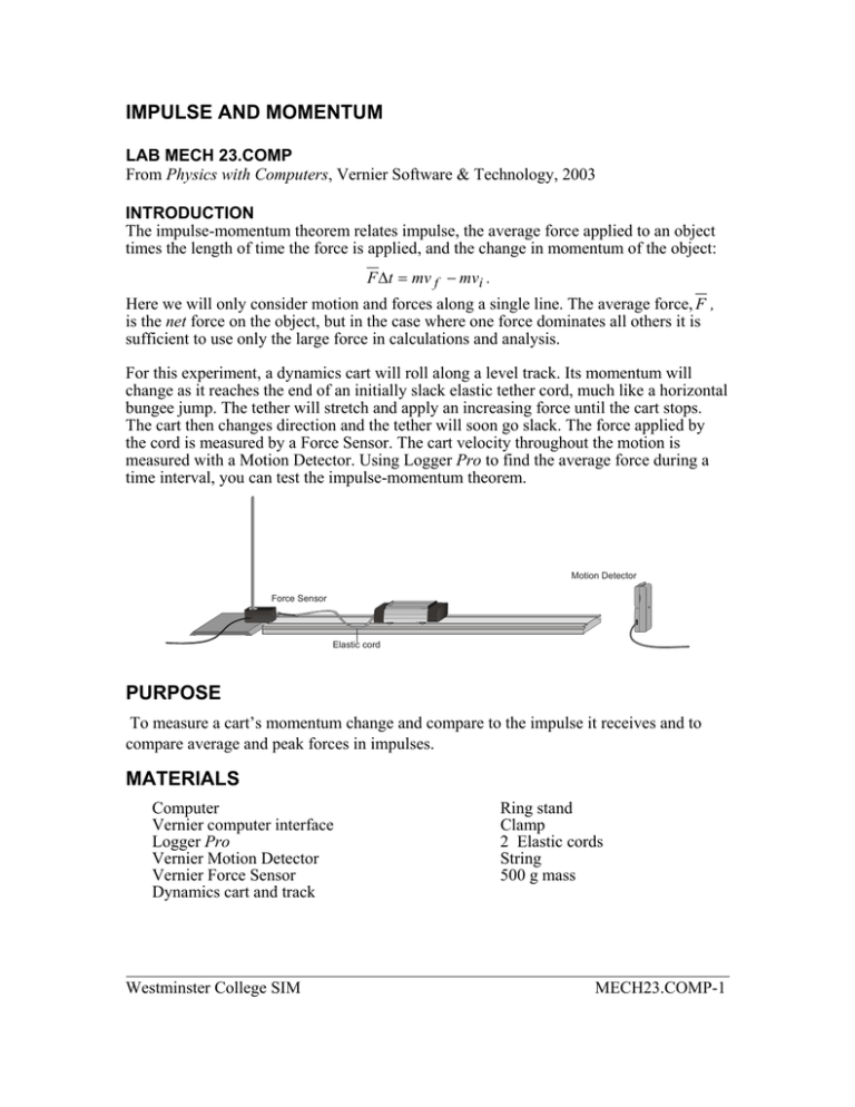
IMPULSE AND MOMENTUM LAB MECH 23.COMP From Physics with Computers, Vernier Software & Technology, 2003 INTRODUCTION The impulse-momentum theorem relates impulse, the average force applied to an object times the length of time the force is applied, and the change in momentum of the object: F ∆t = mv f − mvi . Here we will only consider motion and forces along a single line. The average force, F , is the net force on the object, but in the case where one force dominates all others it is sufficient to use only the large force in calculations and analysis. For this experiment, a dynamics cart will roll along a level track. Its momentum will change as it reaches the end of an initially slack elastic tether cord, much like a horizontal bungee jump. The tether will stretch and apply an increasing force until the cart stops. The cart then changes direction and the tether will soon go slack. The force applied by the cord is measured by a Force Sensor. The cart velocity throughout the motion is measured with a Motion Detector. Using Logger Pro to find the average force during a time interval, you can test the impulse-momentum theorem. Motion Detector Force Sensor Elastic cord PURPOSE To measure a cart’s momentum change and compare to the impulse it receives and to compare average and peak forces in impulses. MATERIALS Computer Vernier computer interface Logger Pro Vernier Motion Detector Vernier Force Sensor Dynamics cart and track Westminster College SIM Ring stand Clamp 2 Elastic cords String 500 g mass MECH23.COMP-1 Impulse and Momentum PRELIMINARY QUESTIONS 1. In a car collision, the driver’s body must change speed from a high value to zero. This is true whether or not an airbag is used, so why use an airbag? How does it reduce injuries? 2. You want to close an open door by throwing either a 400 g lump of clay or a 400 g rubber ball toward it. You can throw either object with the same speed, but they are different in that the rubber ball bounces off the door while the clay just sticks to the door. Which projectile will apply the larger impulse to the door and be more likely to close it? PROCEDURE 1. Measure the mass of your dynamics cart and record the value in the Data Table. 2. Connect the Motion Detector to DIG/SONIC 1 of the interface. Connect the Force Sensor to Channel 1 of the interface. If your Force Sensor has a range switch, set it to 10 N. 3. Open the file “20 Impulse and Momentum” in the Physics with Computers folder. Logger Pro will plot the cart’s position and velocity vs. time, as well as the force applied by the Force Sensor vs. time. 4. Optional: Calibrate the Force Sensor. a. Choose Calibrate ` CH1: Dual Range Force from the Experiment menu. Click . b. Remove all force from the Force Sensor. Enter a 0 (zero) in the Reading 1 field. Hold the sensor vertically with the hook downward and wait for the reading shown for CH1 to stabilize. Click . This defines the zero force condition. c. Hang the 500 g mass from the sensor. This applies a force of 4.9 N. Enter 4.9 in the Reading 2 field, and after the reading shown for CH1 is stable, click . Click to close the calibration dialog. 5. Place the track on a level surface. Confirm that the track is level by placing the lowfriction cart on the track and releasing it from rest. It should not roll. If necessary, adjust the track. 6. Attach the elastic cord to the cart and then the cord to the string. Tie the string to the Force Sensor a short distance away. Choose a string length so that the cart can roll freely with the cord slack for most of the track length, but be stopped by the cord before it reaches the end of the track. Clamp the Force Sensor so that the string and cord, when taut, are horizontal and in line with the cart’s motion. 7. Place the Motion Detector beyond the other end of the track so that the detector has a clear view of the cart’s motion along the entire track length. When the cord is stretched to maximum extension the cart should not be closer than 0.4 m to the detector. Westminster College SIM MECH23.COMP-2 Impulse and Momentum 8. Click Sensor. , select Force Sensor from the list, and click to zero the Force 9. Practice releasing the cart so it rolls toward the Motion Detector, bounces gently, and returns to your hand. The Force Sensor must not shift and the cart must stay on the track. Arrange the cord and string so that when they are slack they do not interfere with the cart motion. You may need to guide the string by hand, but be sure that you do not apply any force to the cart or Force Sensor. Keep your hands away from between the cart and the Motion Detector. 10. Click to take data; roll the cart and confirm that the Motion Detector detects the cart throughout its travel. Inspect the force data. If the peak exceeds 10 N, then the applied force is too large. Roll the cart with a lower initial speed. If the velocity graph has a flat area when it crosses the time-axis, the Motion Detector was too close and the run should be repeated. 11. Once you have made a run with good position, velocity, and force graphs, analyze your data. To test the impulse-momentum theorem, you need the velocity before and after the impulse. Choose an interval corresponding to a time when the elastic was initially relaxed, and the cart was moving at approximately constant speed away from the Force Sensor. Drag the mouse pointer across this interval. Click the Statistics button, , and read the average velocity. Record the value for the initial velocity in your Data Table. In the same manner, choose an interval corresponding to a time when the elastic was again relaxed, and the cart was moving at approximately constant speed toward the Force Sensor. Drag the mouse pointer across this interval. Click the statistics button and read the average velocity. Record the value for the final velocity in your Data Table. 12. Now record the time interval of the impulse. There are two ways to do this. Use the first method if you have studied calculus and the second if you have not. • Method 1: Calculus tells us that the expression for the impulse is equivalent to the integral of the force vs. time graph, or t final F ∆t = ∫ F (t )dt . tinitial On the force vs. time graph, drag across the impulse, capturing the entire period when the force was non-zero. Find the area under the force vs. time graph by clicking the Integral button, . Record the value of the integral in the impulse column of your Data Table. • Method 2: On the force vs. time graph, drag across the impulse, capturing the entire period when the force was non-zero. Find the average value of the force by clicking the Statistics button, , and also read the length of the time interval over which your average force is calculated. The number of points used in the average divided by the data rate of 50 Hz gives the time interval ∆t. Record the values in your Data Table. Westminster College SIM MECH23. COMP-3 Impulse and Momentum 13. Perform a second trial by repeating Steps 10 – 12, record the information in your Data Table. 14. Change the elastic material attached to the cart. Use a new material, or attach two elastic bands side by side. 15. Repeat Steps 10 – 13, record the information in your Data Table. DATA TABLE Mass of cart kg Trial Final Velocity vf Initial Velocity vi Average Force F Duration of Impulse ∆t Impulse Elastic 1 (m/s) (m/s) (N) (s) (N⋅s) 1 2 Elastic 2 1 2 Trial Elastic 1 Impulse F∆t (N⋅s) Change in momentum (kg⋅m /s) or (N⋅s) % difference between Impulse and Change in momentum (N⋅s) 1 2 Elastic 2 1 2 ANALYSIS 1. From the mass of the cart and change in velocity, determine the change in momentum as a result of the impulse. Make this calculation for each trial and enter the values in the second Data Table. Westminster College SIM MECH 23. COMP-4 Impulse and Momentum 2. If you used the average force (non-calculus) method, determine the impulse for each trial from the average force and time interval values. Record these values in your Data Table. 3. If the impulse-momentum theorem is correct, the change in momentum will equal the impulse for each trial. Experimental measurement errors, along with friction and shifting of the track or Force Sensor, will keep the two from being exactly the same. One way to compare the two is to find their percentage difference. Divide the difference between the two values by the average of the two, then multiply by 100%. How close are your values, percentage-wise? Do your data support the impulsemomentum theorem? 4. Look at the shape of the last force vs. time graph. Is the peak value of the force significantly different from the average force? Is there a way you could deliver the same impulse with a much smaller force? 5. Revisit your answers to the Preliminary Questions in light of your work with the impulse-momentum theorem. 6. When you use different elastic materials, what changes occurred in the shapes of the graphs? Is there a correlation between the type of material and the shape? 7. When you used a stiffer or tighter elastic material, what effect did this have on the duration of the impulse? What affect did this have on the maximum size of the force? Can you develop a general rule from these observations? EXTENSIONS 1. Try other elastic materials, doing the same experiment. Westminster College SIM MECH23. COMP-5
