Document 12915593
advertisement

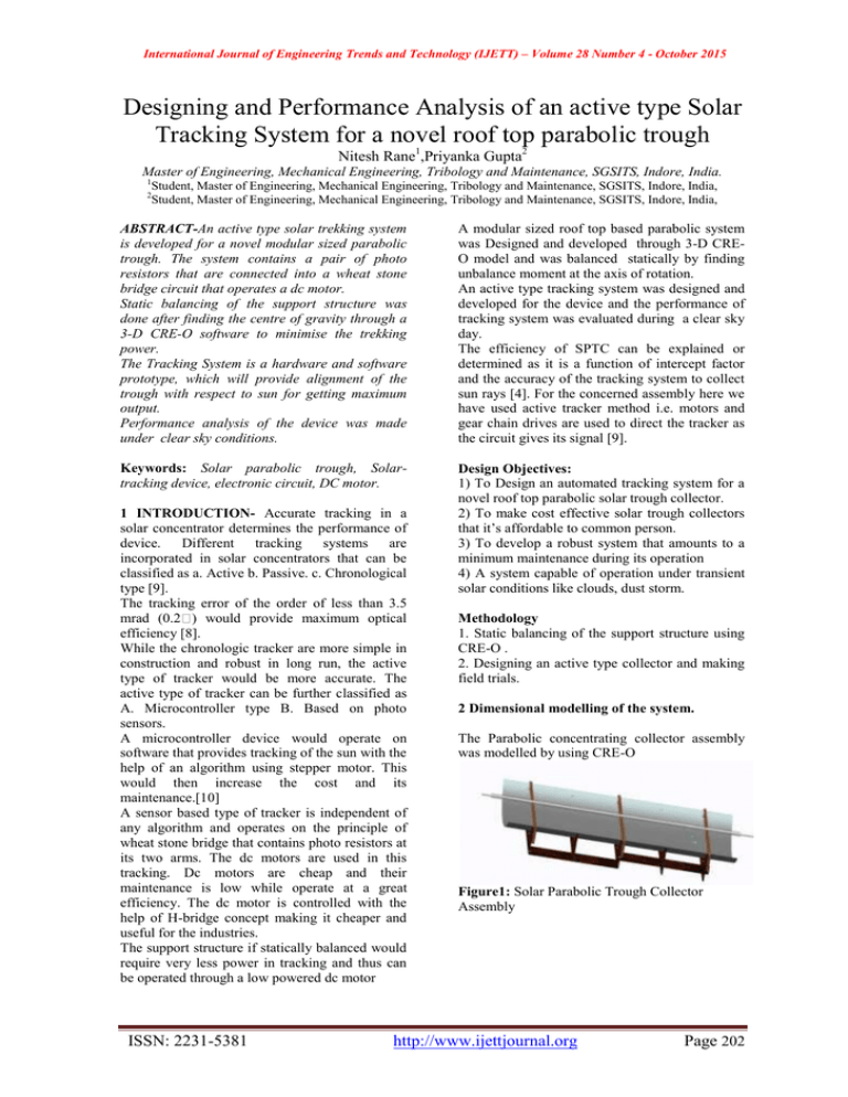
International Journal of Engineering Trends and Technology (IJETT) – Volume 28 Number 4 - October 2015 Designing and Performance Analysis of an active type Solar Tracking System for a novel roof top parabolic trough Nitesh Rane1,Priyanka Gupta2 Master of Engineering, Mechanical Engineering, Tribology and Maintenance, SGSITS, Indore, India. 1 Student, Master of Engineering, Mechanical Engineering, Tribology and Maintenance, SGSITS, Indore, India, Student, Master of Engineering, Mechanical Engineering, Tribology and Maintenance, SGSITS, Indore, India, 2 ABSTRACT-An active type solar trekking system is developed for a novel modular sized parabolic trough. The system contains a pair of photo resistors that are connected into a wheat stone bridge circuit that operates a dc motor. Static balancing of the support structure was done after finding the centre of gravity through a 3-D CRE-O software to minimise the trekking power. The Tracking System is a hardware and software prototype, which will provide alignment of the trough with respect to sun for getting maximum output. Performance analysis of the device was made under clear sky conditions. A modular sized roof top based parabolic system was Designed and developed through 3-D CREO model and was balanced statically by finding unbalance moment at the axis of rotation. An active type tracking system was designed and developed for the device and the performance of tracking system was evaluated during a clear sky day. The efficiency of SPTC can be explained or determined as it is a function of intercept factor and the accuracy of the tracking system to collect sun rays [4]. For the concerned assembly here we have used active tracker method i.e. motors and gear chain drives are used to direct the tracker as the circuit gives its signal [9]. Keywords: Solar parabolic trough, Solartracking device, electronic circuit, DC motor. Design Objectives: 1) To Design an automated tracking system for a novel roof top parabolic solar trough collector. 2) To make cost effective solar trough collectors that it’s affordable to common person. 3) To develop a robust system that amounts to a minimum maintenance during its operation 4) A system capable of operation under transient solar conditions like clouds, dust storm. 1 INTRODUCTION- Accurate tracking in a solar concentrator determines the performance of device. Different tracking systems are incorporated in solar concentrators that can be classified as a. Active b. Passive. c. Chronological type [9]. The tracking error of the order of less than 3.5 mrad (0.2 ) would provide maximum optical efficiency [8]. While the chronologic tracker are more simple in construction and robust in long run, the active type of tracker would be more accurate. The active type of tracker can be further classified as A. Microcontroller type B. Based on photo sensors. A microcontroller device would operate on software that provides tracking of the sun with the help of an algorithm using stepper motor. This would then increase the cost and its maintenance.[10] A sensor based type of tracker is independent of any algorithm and operates on the principle of wheat stone bridge that contains photo resistors at its two arms. The dc motors are used in this tracking. Dc motors are cheap and their maintenance is low while operate at a great efficiency. The dc motor is controlled with the help of H-bridge concept making it cheaper and useful for the industries. The support structure if statically balanced would require very less power in tracking and thus can be operated through a low powered dc motor ISSN: 2231-5381 Methodology 1. Static balancing of the support structure using CRE-O . 2. Designing an active type collector and making field trials. 2 Dimensional modelling of the system. The Parabolic concentrating collector assembly was modelled by using CRE-O Figure1: Solar Parabolic Trough Collector Assembly http://www.ijettjournal.org Page 202 International Journal of Engineering Trends and Technology (IJETT) – Volume 28 Number 4 - October 2015 TABLE I Components of solar parabolic trough Component Diameter of tube (od) Width Focal Length Length Aperture Area Tracking mechanism type Mode of tracking TABLE III Specification of absorber supporting rod Dimensions Typical dimension 25 cm 100 cm 30 cm 300 cm 3 m2 Electronic N-S horizontal Individual components were designed in 3 D and then were assembled to determine the unbalance moment that occurs at the hinge point. The components modelled were 1. Support structure 2. Absorber support 3. Absorber pipe along with glass cover 4. reflector sheet Length of the Plate Thickness of the Plate Hole diameter for Absorber Pipe Value 1120 mm 25 mm 9 mm Absorber pipe: The absorber is design according to the limitation of the collector, with considering parameters like piping, working fluid velocity, fabrication and heat loss. Thereby, the absorber is fabricated by the seamless pipe, with the inner diameter of 24 mm, outer diameter 25 mm and 3680 mm in length Support structure of SPTC Model of Absorber pipe TABLE IV Specifications of Absorber Pipe Model of supporting frame Ply-wood specimens were taken in order to create a base for parabolic trough. TABLE II Specifications of Support frame Dimension Length of the Support frame Breadth of the Support frame Thickness of the plywood Value 2420 mm 1000 mm 20 mm Dimension Inner diameter of the Pipe Outer diameter of the Pipe Length of the Pipe Material Coating Wall Thickness Value 21 mm 23 mm 3680 mm Stainless Steel Black Chrome 2 mm Reflector Stainless steel-304 : To obtain the desired parabolic trough stainless steel sheet is used. Absorber support: In order to support the absorbing rod the angled bars are attached to the supporting frame with the help of nut and bolts. These bars are 3 in no. to properly locate the absorbing rod. Stainless steel trough Specifications of Absorbing Rod Supporter: ISSN: 2231-5381 In parabolic trough the most costly part is reflector. The life of reflector should be long and http://www.ijettjournal.org Page 203 International Journal of Engineering Trends and Technology (IJETT) – Volume 28 Number 4 - October 2015 handling should be easy so that the maintenance cost and the system cost can be reduced. Stainless steel has a long life and low handling as compare to glass. Schematic diagram of active tracking control Open chain drive mechanism Sun tracking Mechanism: To calculate the length of open chain drive Working- The circuit controlling of the SPT has two main divisions: The first division is controlled by sensors. The second division is controlled by motor. Sensors- It contains 4 LDR connected in wheat stone bridge concept. A part of bridge will be receiving more sunlight hence wheat stone bridge concept can be incorporated. The output of the bridge is connected to an opamp which is further connected to optocoupler used to drive the second division of the circuit. Where δ1 = Radius of Larger Sprocket = 200 mm δ2 = Radius of Smaller Sprocket = 70 mm x = Centre distance = 470 mm. L = π (100+35) + (2´470) + [(100-35)²/470] = 3405mm Actual length of chain = 3.405 m. Lumped mass system: static balancing: Motor- To drive the SPT a DC-motor is used here. The output of optocoupler is used for activating the motor circuit. Motor is driven by an H-Bridge circuit because it is required for the SPT to move clockwise and anti-clockwise as desired. H-bridge is appropriate for the desired operation taking into consideration the cost of the complete arrangement. DESIGN OF SPROCKET & CHAIN MECHANISMThis arrangement operates with the help of DC Motor. Consider a large Sprocket or gear attached to parabolic trough. Let a chain drive be meshed with both sprockets, one mounted on the DC Motor & another on parabolic trough. ISSN: 2231-5381 http://www.ijettjournal.org Page 204 International Journal of Engineering Trends and Technology (IJETT) – Volume 28 Number 4 - October 2015 To minimise the torque required by the parabolic trough static balancing is done. In this a lumped mass is hanged through the centre axis of parabolic trough. When conducting the experiments a jerk was noticed in the operation of the parabolic trough. To overcome that jerk so that it may not cause problems to the electronic and mechanical components a shock absorbing material was added to the support stand of the parabolic trough. The assembly is required to bring to its initial position at the end of the day. The balancing of parabolic trough is explained by eqn given below: M1R1+M2R2=M3R3 where: M1=weight of receiver tube and glass tube M2=weight or reflector sheet and frame M3=weight of applied load R1and R2= vertical length from the centre axis of upper side R3=vertical length below from the centre axis of parabolic trough. Experimental setup and testing-In this experiment, water was filled from one end of the SS absorber pipe with other end opened. The temperature of water was measured by using electronic thermometer and tabulated for every hour from 09:00 am to 04:00 pm. The SPTC was rotated using a DC motor, sprocket and chain mechanism to keep the sun rays perpendicular to the absorber pipe. When conducting the experiments jerks were noticed. To overcome that jerk so that it may not cause problems to the electronic and mechanical components a shock absorbing material was added to the support stand of the parabolic trough. ISSN: 2231-5381 Experimental Setup of SPTC Conclusion-Though two axis tracking mode provides greater accuracy and is more likely to trace the sun more accurately. The application of two axis tracking can only be justified if the capital and running cost invested in it can give the desired output variation. Thus, a single tracking mode is employed to track the solar irradiation. Here an electro-mechanical system is built with the basics like wheat-stone bridge and H-bridge concept. This reduces maintenance cost and hence proving it useful for the application in small scale industries as the temperature of 150ᶱC is achieved with no difficulty. References [1] Keshav Pratap, Dr. Bhupendra Gupta, Brahman Singh Bhalavi, Mohit Pandya: Performance Analysis of Automatic Hybrid Solar Tracking System with Different Types of Solar Cell Materials (2014). [2] Saad D. Odeh & Hosni I. Abu-Mulaweh: Design and development of an educational solar tracking parabolic trough collector system (2013). [3] Koussa, M., Cheknane, A., Hadji, S., Haddadi, M. and Noureddine, S., Measured and modelled improvement in solar energy yield from flat plate photovoltaic systems utilizing different tracking systems and under a range of environmental conditions (2011). [4] P.Naidoo Mangosuthu Technikon, T.I. van Niekerk PE Technikon Faculty of Engineering: Electrical Durban South Africa,(2002). [5] Hemant Kumar Nayak1*, Manoj Kumar2, Nagendra Prasad3, Rashmi Rekha Behera4: Fabrication and Experimental Study on Two-Axis Solar Tracking (2011). [6] Bin-Juine Huang, Yin-Chen Huang, Guan-Yu Chen: Improving Solar PV system Efficiency using 1-axis 3position Tracking system. [7] Rockwell automation: NREL technical report. [8] P. Naidoo, M. Brooks, T.I. van Niekerk: Intelligent Control and Tracking of Parabolic Trough Solar Collector. [9] Ankit N. Parmar, Vinod S. Gautam: Passive Solar Tracking System. [10] Arnab Samanta, RachitVarma, Shrikant Bhatt Chronological Single Axis Solar Tracker International Journal of Engineering Trends and Technology (IJETT) – Volume 21 Number 4 – March 2015. http://www.ijettjournal.org Page 205


