Setup Development and Feasibility Check of Single Point Incremental Forming
advertisement
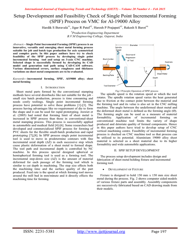
International Journal of Engineering Trends and Technology (IJETT) – Volume 20 Number 4 – Feb 2015 Setup Development and Feasibility Check of Single Point Incremental Forming (SPIF) Process on VMC for Al-19000 Alloy Hardik S Beravala#1, Jigar R Patel#2, Haresh P Prajapati#3, Rakesh S Barot#4 # Production Engineering Department B.V.M Engineering College, Gujarat, India Abstract: - Single Point Incremental Forming (SPIF) process is an innovative, versatile and emerging sheet metal forming process suitable for job and batch type production for axis symmetrical and complex parts. In this paper authors have try to check feasibility of the SPIF process by developing single point incremental forming tool and setup on 3-axis CNC machine. Selected shape is successfully formed by developing its CAD model and generation tool path using CAD-CAM software. Various dimensional errors, surface roughness and thickness variations on sheet metal components are to be evaluated. Keywords—incremental forming, SPIF, Al19000 alloy; sheet metal forming I. INTRODUCTION Sheet metal parts formed by the conventional stamping methods have several drawbacks like not suitable for the job small size batch production, process is time consuming and needs costly toolings. Single point incremental forming process have potential to solve these problems [1]-[3]. The process having advantages like no requirement of die to form the shape and it can be used for rapid prototyping. Jeswiet et al. (2005) had noted that forming limit of sheet metal is increased in SPIF process than those in conventional-sheet metal stamping process. This process is successfully applied in automobile and medical field [4]-[6]. Some researchers had developed and commercialized SPIF process for forming of PVC sheets for the flexible small-batch production and rapid prototyping [7],[8]. In SPIF process single point incremental tool is used to move in predetermine contours with fine incremental axial depth (ΔZ) in each successive step which cause plastic deformation of a sheet metal to formed shape. The tool path and incremental depth is controlled by NC machine. In this process special designed spherical or hemispherical forming tool is used as a forming tool. The incremental step-down size (ΔZ) is the amount of material deformed for each passage of the forming tool which is similar to cut depth in machining. The step size effects both the machining time and the surface quality of the part produced. Feed rate is the speed at which forming tool moves around the mill bed in mm/minute and it directly effects the machining time for forming. ISSN: 2231-5381 Fig.1 Principle Operation of SPIF process The spindle speed is the rotation speed at which the tool rotates. The spindle rotation speed varies the heat generated due to friction at the contact point between the material and the forming tool and its value is also set in the CNC milling machine. The angle between the undeformed sheet metal and the deformed sheet metal is defined as the forming angle (Ø). The forming angle can be used as a measure of material formability. Application of incremental forming on conventional machine tool limits the variety of shape produced and detoriate quality of formed components. Hence in this paper authors have tried to develop setup of CNC vertical machining centre. Feasibility of incremental forming process is checked on CNC machine tool so that process can be utilized to its potential. Aluminium 19000 alloy sheet material is selected as a sheet material due to its higher formability and wide automobile applications. II. SPIF SETUP DEVELOPMENT The process setup development includes design and fabrication of sheet metal holding fixture and incremental forming tool. DEVELOPMENT OF FIXTURE Fixture is designed to hold 150 mm x 150 mm size sheet metal during the process. Fig. 2 shows computer aided models of various fixture parts and assembly. Assembly components are successively fabricated based on CAD drawing made from their models. http://www.ijettjournal.org Page 197 International Journal of Engineering Trends and Technology (IJETT) – Volume 20 Number 4 – Feb 2015 Fig. 4. CAD model of formed component. Fig.2. CAD model of fixture component and Assembly DEVELOPMENT OF SPIF TOOL The tool was made from stainless steel 304 hardened to 62 HRC with hemispherical tip having diameter 14 mm. Tool diameter is machined on CNC turning centre. Hemispherical tip is polished by buffing for more accurate result. Fig. 3 shows CAD model of tool design. Sophisticated CAM software is used to generated tool path for the component to be formed by slicing it in to number of horizontal layers as per given incremental depth (ΔZ). Forming tool is moved according the tool path generated as shown in Fig. 5. Fig. 5. Tool path generation for forming tool IV. FEASIBILITY CHECK Fig.3. CAD model of SPIF tool 0.9 mm thick Aluminium 19000 alloy sheet material is selected as a sheet material for forming. It constrains 1% Si 0.2 %Cu 0.05% Mn 0.1%Cr 0.1% Zn and 98.55% Al. III. FORMED COMPONENT SHAPE SELECTION AND TOOL PATH GENERATION Various researchers had used rectangular, square, conical, circular, spherical formed shapes in their experiments [9]-[11]. It is decided that shape of formed components having combined feature of square and spherical geometry to get output in single formed part. Fig. 4 shows CAD model of shape by combine two (rectangle and circular conical) shape because of to find out the effect of input parameter on curved as well as straight wall. To check a feasibility spindle speed, tool feed rate and incremental depth is selected as an input machining parameters. As per generated tool path and selected machining parameters like spindle speed 2750 rpm, tool feed rate 1400 mm/min and incremental depth 0.15mm part program is developed. On Jyoti CNC make vertical machining centre model VMC 430 setup is installed as shown in Fig. 6 and experiment is performed. Oil is used to reduce the friction between tool and sheet during forming process. Various dimensional errors, surface roughness and thickness distribution is measured and evaluated on the formed component for the selected machining parameters. Fig. 6. Experimental Setup on VMC ISSN: 2231-5381 http://www.ijettjournal.org Page 198 International Journal of Engineering Trends and Technology (IJETT) – Volume 20 Number 4 – Feb 2015 V. RESULT AND DISCUSSION REFERENCES The actual dimensions of the formed component are measured and they are compared with CAD model dimensions. Comparison is shown in Table I. TABLE I [1] [2] COMPARISON CAD MODEL DIMENSIONS AND ACTUAL DIMENSIONS [3] CAD model Dimensions (mm) Length Width Height Slop angle 190.5 190.5 17 20°. Actual obtained Dimension (mm) 190.0 190.0 16 19.5°. Error (%) 0.27 0.27 5.88 2.5 Surface roughness of the formed component is measured using the Mitutoyo SJ201 surface roughness tester. Surface roughness is found 0.89µm along the tool path and 3.86 µm across the tool path. Higher value of roughness along tool path is due to the tool marks produced on the sheet during the forming along the tool path. Thickness of the component after forming is measured by digital venire calliper. Thickness of sheet is found 0.82 mm at the wall. It is also observed that thickness is uniformly distributed at the wall and it is less than the undeformed thickness of sheet. Thickness distribution is uniformed due to constant incremental axial depth of tool given during forming while thickness is reduced at wall due to starching of the sheet during deformation. [4] [5] [6] [7] [8] [9] J.Cao, Y.Huang, N.V.Reddy, R.Malhotra, Y.Wang, ―Incremental sheet metal forming: advances and challenges‖, Proceedings of the International Conference on Technology of Plasticity, ICTP2008, 2008, pp.1967–1982. W.C.Emmens, G.Sebastiani, A.H.vanden Boogaard, The technology of incremental sheet forming—a brief review of the history, Journal of Materials Processing Technology, 210 (2010)981–997. R. Malhotra, L.Xue, T.Belytschko, J.Cao, Mechanics of fracture in single point incremental forming,Journal of Materials Processing Technology, 212(2012) 1573–1590. Jeswiet J, Micari F, Hirt G, Bramley A, Duflou A, Allwood J (2005) Asymmetric single point incremental forming of sheet metal. CIRP Annals 54(2):623–649. Hussain G, Gao L, Hayat N, Ziran X. A new formability indicator in single point incremental forming. J Mater Process Technol 2009;209:4237–42. G. Ambrogio, L. De Napoli, L. Filice, F. Gagliardi, M. Muzzupappa, Application of incremental forming process for highly customized medical product manufacturing, Journal of Materials Processing Technology, 162–163 (2005) 156–162. Franzen,V.,Kwiatkowski,L.,Martins,P.A.F.,Tekkaya,A.E.,2008a.Single pointincre-mental forming of PVC .Journal of Materials Processing Technology 209,462e469. Martins PAF, Kwiatkowski L, Franzen V, Tekkaya AE, Kleiner M. Single point incremental forming of polymers. CIRP Ann – Manuf Technol 2009;58:229–32. G. Hussain, L. Gao ―A novel method to test the thinning limits of sheet metals in negative incremental forming‖- International Journal of Machine Tools & Manufacture 47 (2007) 419–435 Fig.7. Measurement of Thickness VI. CONCLUSION Single point incremental forming setup is successfully developed on CNC machining centre and feasibility of the process is checked. Errors in the dimensions of the formed component found reasonably less. Variation in the roughness along and across the tool path direction is found. Thickness distribution is also found uniform at the wall. More work required to be done for further improvement in the surface finish of formed component by this process. ISSN: 2231-5381 http://www.ijettjournal.org Page 199
