5 Separation Processes
advertisement

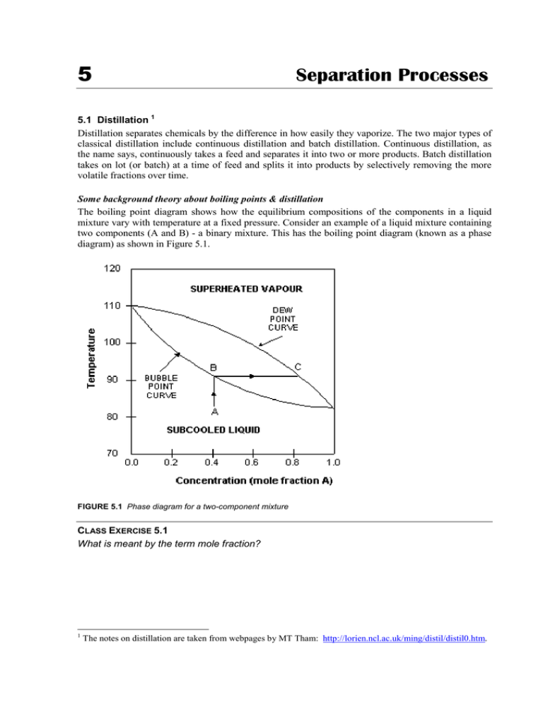
5 Separation Processes 5.1 Distillation 1 Distillation separates chemicals by the difference in how easily they vaporize. The two major types of classical distillation include continuous distillation and batch distillation. Continuous distillation, as the name says, continuously takes a feed and separates it into two or more products. Batch distillation takes on lot (or batch) at a time of feed and splits it into products by selectively removing the more volatile fractions over time. Some background theory about boiling points & distillation The boiling point diagram shows how the equilibrium compositions of the components in a liquid mixture vary with temperature at a fixed pressure. Consider an example of a liquid mixture containing two components (A and B) - a binary mixture. This has the boiling point diagram (known as a phase diagram) as shown in Figure 5.1. FIGURE 5.1 Phase diagram for a two-component mixture CLASS EXERCISE 5.1 What is meant by the term mole fraction? 1 The notes on distillation are taken from webpages by MT Tham: http://lorien.ncl.ac.uk/ming/distil/distil0.htm. 5. Separation Processes CLASS EXERCISE 5.2 (a) Given that the boiling point of A is that at which the mole fraction of A is 1, estimate the boiling points of compounds A & B. (b) Which is the more volatile component? The dew point is the temperature at which the saturated vapour starts to condense. The bubble point is the temperature at which the liquid starts to boil. CLASS EXERCISE 5.3 What is the (a) bubble point and (b) dew point for a 1:1 mix of the compounds? When a mixture is the sub-cooled liquid or superheated vapour region, its composition does not change on heating/cooling. However, when a liquid is heated to its bubble point, it behaves as for a pure liquid in that the temperature doesn’t rise as the liquid boils, in this case, reaches the dew point. As it does, the composition of the vapour will be different. CLASS EXERCISE 5.4 (a) What happens to the mixture of 0.4 mole fraction A when it is heated to boiling? (b) What is the composition of the vapour that forms from 0.4 mole fraction A liquid? (c) If this vapour is condensed and re-heated, what will the resulting vapour be? 34 5. Separation Processes This difference between liquid and vapour compositions is the basis for distillation operations. The above example describes a binary systems (two components) because it is simple to explain the basic principles. Multi-component systems are complex, but behave in similar ways. However, azeotrope mixtures are different. These are mixtures which do not differ in the composition of the liquid and the vapour. Two examples are benzene-ethanol and chloroformpropanone. CLASS EXERCISE 5.5 What is the significance of an azeotrope mixture in distillation? Azeotropes have differently shaped phase diagrams, which show two dew-bubble point curves, joined at a central point, which the azeotropic composition, as shown in Figure 5.2. Now the cycle of boiling and condensing leads not to a pure liquid, but to the point where the composition of vapour and liquid are the same. FIGURE 5.2 Phase diagram for an azeotropic mixture They can only be separated by the addition of a third component, which “breaks” the azeotrope. Distillation towers Distillation towers are made up of several components, each of which is used either to transfer heat energy or enhance material transfer. A typical distillation contains several major components: • a vertical shell where the separation of liquid components is carried out • column internals such as trays/plates and/or packings which are used to enhance component separations • a reboiler to provide the necessary vaporisation for the distillation process • a condenser to cool and condense the vapour leaving the top of the column • a reflux drum to hold the condensed vapour from the top of the column so that liquid (reflux) can be recycled back to the column 35 5. Separation Processes The vertical shell houses the column internals and together with the condenser and reboiler, constitute a distillation column. A schematic of a typical distillation unit with a single feed and two product streams is shown in Figure 5.3. FIGURE 5.3 Components of a distillation tower Figure 5.4 shows the processes occurring in a distillation tower. The feed containing the components to be separated enters around the middle of the column. The feed can be in any state from cold liquid to superheated vapour. FIGURE 5.4 (a) The distillation process 36 5. Separation Processes Liquid and vapour are in counter-current contact throughout the column as the liquid flows down and the vapour flows up the column. At each distillation stage, some of the vapour moving up the column is condensed and this in turn evaporates some of the liquid moving down the column. If there are two components in the feed, then a greater amount of the less volatile component will condense at each stage and a greater amount of the more volatile component will evaporate. The rectifying section is the name given to the stages above the feed point, where the concentration of the more volatile component increases in both the liquid and the vapour. FIGURE 5.4 (b) & (c) The distillation process 37 5. Separation Processes The stripping section is the name given to the stages below the feed point, where the concentration of the more volatile component decreases in both the liquid and the vapour. The overhead vapour containing the most volatile components from the feed, moves from the top of the column to the condenser. In this heat exchanger, water is used to condense the vapour. FIGURE 5.4 (d) & (e) The distillation process (cont’d) 38 5. Separation Processes The liquid from the condenser is split into two parts: (a) the reflux is fed back to the column (b) the overhead product contains liquid with a composition specified in the column design The ratio of flowrates of the reflux to the overhead product is called the reflux ratio and is an important parameter in the design and operation of any distillation column. The bottom liquid containing the least volatile components in the feed, flows from the base of the column to the reboiler. In this heat exchanger, steam is used to vaporise some of the liquid, which flows back up the column. The amount of heat fed to the reboiler determines the vapour flow up the column. FIGURE 5.4 (f) & (g) The distillation process (cont’d) 39 5. Separation Processes The bottom product has a specified composition, fixed during the design of the column, and is the second product stream from a distillation column. Columns for complex mixtures can have take-off points at the different levels up the column. FIGURE 5.4 (h) The distillation process (cont’d) Trays The condensation/vaporisation process in tray-based columns occurs in trays, which are horizontal plates across the column, with openings to allow vapour to rise and liquid to fall, as shown in Figure 5.5(a). A weir on the tray ensures that there is always some liquid (holdup) on the tray and is designed such that the holdup is at a suitable height, e.g. such that the bubble caps are covered by liquid. The bubble cap (Figure 5.5(b) prevents the rising vapour from passing straight through the plate, forcing it to interact with the liquid. vapour from plate below FIGURE 5.5 (a) Column trays (b) Bubble cap T 40 5. Separation Processes Packings An alternative to trays, packings are passive devices that are designed to increase the interfacial area for vapour-liquid contact, as shown in Figure 5.6. FIGURE 5.6 Different types of packings These strangely shaped pieces are made from stainless steel, and supposed to impart good vapourliquid contact when a particular type is placed together in numbers, without causing excessive pressure-drop across a packed section. This is important because a high pressure drop would mean that more energy is required to drive the vapour up the distillation column. Packings versus trays A tray column that is facing throughput problems may be de-bottlenecked by replacing a section of trays with packings. This is because: • packings provide extra area for liquid-vapour contact • efficiency of separation is increased for the same column height • packed columns are shorter than trayed columns Factors affecting distillation column operation The performance of a distillation column is determined by many factors. Some of these will be discussed below to give an idea of the complexity of the distillation process. FEED CONDITIONS The state of the feed mixture and feed composition affects the operating lines and hence the number of stages required for separation. It also affects the location of feed tray. During operation, if the deviations from design specifications are excessive, then the column may no longer be able handle the separation task. To overcome the problems associated with the feed, some column are designed to have multiple feed points when the feed is expected to containing varying amounts of components. REFLUX CONDITIONS As the reflux ratio is increased, the gradient of operating line for the rectification section moves towards a maximum value of 1. Physically, what this means is that more and more liquid that is rich in the more volatile components are being recycled back into the column. Separation then becomes better and thus less trays are needed to achieve the same degree of separation. Minimum trays are required under total reflux conditions, i.e. there is no withdrawal of distillate. On the other hand, as reflux is decreased, the operating line for the rectification section moves towards the equilibrium line. The ‘pinch’ between operating and equilibrium lines becomes more pronounced and more and more trays are required. 41 5. Separation Processes VAPOUR FLOW CONDITIONS Adverse vapour flow conditions can cause: • foaming – the expansion of liquid due to passage of vapour or gas; although it provides high interfacial liquid-vapour contact, excessive foaming often leads to liquid build-up on trays; in some cases, foaming may be so bad that the foam mixes with liquid on the tray above • entrainment – where the liquid carried by vapour up to the tray above and is again caused by high vapour flow rates; it is detrimental because tray efficiency is reduced; lower volatile material is carried to a plate holding liquid of higher volatility; it could also contaminate high purity distillate • weeping/dumping – caused by low vapour flow; the pressure exerted by the vapour is insufficient to hold up the liquid on the tray; therefore, liquid starts to leak through perforations; excessive weeping will lead to dumping, where the liquid on all trays will crash (dump) through to the base of the column (via a domino effect) and the column will have to be re-started. • flooding – brought about by excessive vapour flow, causing liquid to be entrained in the vapour up the column. The increased pressure from excessive vapour also backs up the liquid in the downcomer, causing an increase in liquid holdup on the plate above WEATHER CONDITIONS Most distillation columns are open to the atmosphere. Although many of the columns are insulated, changing weather conditions can still affect column operation. Thus the reboiler must be appropriately sized to ensure that enough vapour can be generated during cold and windy spells and that it can be turned down sufficiently during hot seasons. The same applies to condensers. Factors determining the design of a column • the number of stages (see Figure 5.7) • the location of the feed tray • tray spacings • column diameter • internal configurations (packing vs trays) • heating and cooling requirements 0.7 0.6 0.5 0.4 Mole fraction Top 0.3 Bottom 0.2 0.1 0 8 10 12 Number of Stages FIGURE 5.7 Effect of number of stages on separation (mole fraction of more volatile component) 42 5. Separation Processes 5.2 Drying and evaporation Drying is done industrially for a number of reasons: • to reduce product weight and therefore transport costs • to make a material easier to handle, eg fertiliser, since it will be less sticky • to minimise corrosion • to reduce the activity of micro-organisms on biological materials Moisture exists in two forms: free and bound. Free moisture is the liquid in the exterior surface of the materials, and is relatively easy to remove. Bound water is held to the material by strong hydrogen bonds, and can be contained within small capillaries, cells, fibres etc. It is less volatile than free water, and is consequently harder to remove. CLASS EXERCISE 5.6 What factors affect the rate of drying? Table 5.1 summarises the properties of some of the common types of drying equipment. TABLE 5.1 Types of driers Name Mode of operation Applications Tray Materials placed on trays, and hot air passed over Batch drying Fluidised bed Hot air passed through the material, creating a turbulent “cloud” of material Powdered materials Spray Aerosol of liquid sprayed through stream of hot air Instant coffee, detergent powders Drum Thin film of fluid material run onto the outside of a heated rotating drum Inorganic solutions, slurries and pastes Rotary Similar to a drum, except material fed into the inside of tilted rotating cylinder, which has hot air fed through Relatively dry granular materials Freeze drying is used where the slow, heated removal of water will not work efficiently, or where the elevated temperatures will cause degradation of the product or loss of other volatiles. It is particularly important in the food and pharmaceutical industries. It relies on sublimation of ice at low pressures, with gentle warming causing the ice to turn into steam, rather than liquid water. This stops the transport of dissolved salts in the centre of the material, causing changes in composition, texture and flavour. 43 5. Separation Processes In general, drying means the removal of all (or as much as possible) of volatile liquids from materials, leaving a solid residue. Evaporation is generally done on liquids, and is essentially incomplete drying, where not all of the liquid is removed, leaving a more concentration solution. The most common types of evaporators are in fact heat exchangers, with steam passing through the shell, and the liquid to be evaporated through the tubing. The early evaporators were horizontal, but this made it difficult to control the time spent by the liquid inside – the residence time – a major factor in determining the amount of solvent removed. More common these days are vertical evaporators, where the liquid to be concentrated is allowed to fall by gravity in a thin film on the inside of the tubes – falling film – or is pumped upwards through the tubing – rising film. In the falling film evaporator, the dilute liquid flows over a weir at the top of the tubes which causes it to form a film. A vacuum at the top is used to draw the vapour away, while the concentrate runs out the bottom. In the rising film type both the concentrate and the vapour automatically rises and are separated by gravity in a separate unit (the separator) is removed. The film is created by the action of vapour bubbles which push the liquid against the tube walls. CLASS EXERCISE 5.7 Why do both these methods rely on a film of liquid? One other very common evaporator is the flash evaporator, which uses a high vacuum, which reduces the boiling point of the solvent, allowing much temperatures to be used. The type of liquid to be concentrated determines which type of evaporator is used: • rising film – ideal for foaming liquids • falling film – shorter residence times and thinner films make it excellent for mildly heatsensitive liquids, such as fruits juices, and also for viscous liquids • flash – the lower temperatures mean that very heat-sensitive liquids, such as milk, can be evaporated 5.3 Filtration Filtration is the removal of solids from a fluid by passing it through some medium upon which the solid particles are deposited. Industrially, the variations between different filtration situations are substantial: • nature of the fluid • particle size of the solid • solids content • temperature • pressure • which material (solid or fluid) is the required one (or possibly both are) 44 5. Separation Processes Terminology Filter medium – the porous material that retains the solids and allows the fluid to pass through Filter cake – the solid that builds up on the filter medium Filtrate – the fluid that passes through Slurry – the mixture of solid and fluid to be filtered Filter aid – a solid material used to keep the filter cake porous You might think that the filter medium is the material that “filters” out the solid, but it is really only the support for the filter cake, and it is the first few layers of filter cake that are the real filter. Examples of materials used to construct the filter medium are woven materials, such as wool, nylon, and metal, perforated metal sheeting, rigid porous material such as ceramics, and non-woven materials such as paper and fibreglass. CLASS EXERCISE 5.8 What factors influence the rate of filtration? If pressure is applied to the process, then it is most common that it will be built up gradually over time, squeezing hardest when the filter cake is at its thickest. Coarse particles are readily filtered under most situations, but fine particles clog up the filter medium very quickly, and prevent further flow. Therefore, in situations where it is known that this problem is likely to occur, a filter aid is used. Filter aids are fine particulate solids, with low compressibility and considerable internal space (eg channels). Examples are diatomaceous earth and cellulose. The filter aid is most commonly filtered first, so that the medium is coated with a thin cake of porous material, which is not readily clogged by the fine particles in the slurry. The most common type of filtration device is the filter press, often called the plate and frame filter. It has solid plates alternating with hollow frames which have a filter medium on each side, as shown in Figure 5.8. The slurry is pumped in through channels which have exits points in the centre of the frames. The filtrate passes through the filter medium and exits via taps. When the frames fill with filter cake, the press is opened, and the cake falls out. Other means of separating solids from liquids are sedimentation tanks and centrifuges. The former is very commonly used in waste treatment, and it will be covered in that chapter. 45 5. Separation Processes filtrate filter medium on frame plate FIGURE 5.8 Frame and plate filter press What You Need To Be Able To Do • define important terminology • explain the meaning of vapour-liquid phase diagrams • draw a schematic diagram showing the components of a distillation tower and explain the function of each component • explain how a distillation tower works • list factors affecting the design and performance of a distillation tower • list reasons for drying materials • describe common drying equipment • explain how freeze drying differs from normal evaporative drying • briefly describe the operation of ONE common evaporator • list factors that affect the efficiency of filtration • briefly describe the operation of ONE common filtration device 46


