Interconnection of Networks: Internetwork
Internet, Standards, and Network Models
Interconnection of Networks: Internetwork
Today, it is very rare to see a LAN , a MAN (metropolitan area network), or a
LAN in isolation; they are connected to one another. When two or more networks are connected, they become an internetwork, or internet.
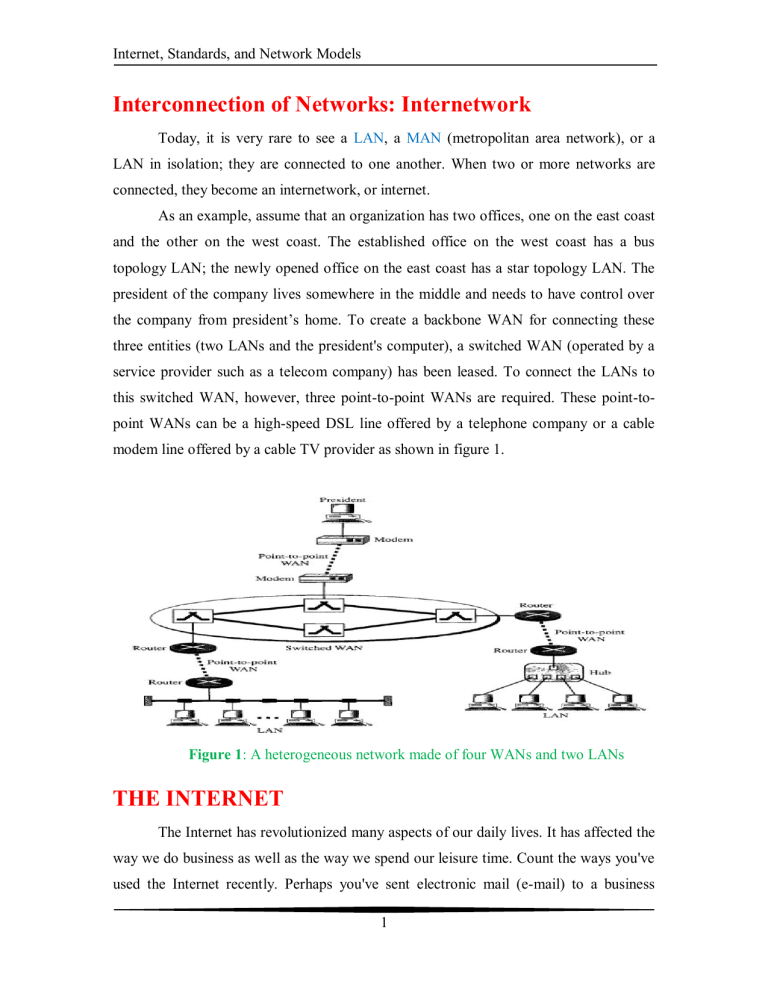
As an example, assume that an organization has two offices, one on the east coast and the other on the west coast. The established office on the west coast has a bus topology LAN; the newly opened office on the east coast has a star topology LAN. The president of the company lives somewhere in the middle and needs to have control over the company from president’s home. To create a backbone WAN for connecting these three entities (two LANs and the president's computer), a switched WAN (operated by a service provider such as a telecom company) has been leased. To connect the LANs to this switched WAN, however, three point-to-point WANs are required. These point-topoint WANs can be a high-speed DSL line offered by a telephone company or a cable modem line offered by a cable TV provider as shown in figure 1.
Figure 1 : A heterogeneous network made of four WANs and two LANs
THE INTERNET
The Internet has revolutionized many aspects of our daily lives. It has affected the way we do business as well as the way we spend our leisure time. Count the ways you've used the Internet recently. Perhaps you've sent electronic mail (e-mail) to a business
1
Internet, Standards, and Network Models associate, paid a utility bill, read a newspaper from a distant city, or looked up a local movie schedule--all by using the Internet. Or maybe you researched a medical topic, booked a hotel reservation, chatted with a fellow, or comparison-shopped for a car. The
Internet is a communication system that has brought a wealth of information to our fingertips and organized it for our use.
The Internet is a structured and organized system. We begin with a brief history of the Internet. We follow with a description of the Internet today.
A Brief History
A network is a group of connected communicating devices such as computers and printers. An internet (note the lowercase letter i) is two or more networks that can communicate with each other. The most notable internet is called the Internet (uppercase letter I), a collaboration of more than hundreds of thousands of interconnected networks.
Private individuals as well as various organizations such as government agencies, schools, research facilities, corporations, and libraries in more than 100 countries use the
Internet. Millions of people are users. Yet this extraordinary communication system only came into being in 1969.
In the mid-1960s, mainframe computers in research organizations were standalone devices. Computers from different manufacturers were unable to communicate with one another. The Advanced Research Projects Agency (ARPA) in the
Department of Defense (DoD) was interested in finding a way to connect computers so that the researchers they funded could share their findings, thereby reducing costs and eliminating duplication of effort.
In 1967, at an Association for Computing Machinery (ACM) meeting, ARPA presented its ideas for ARPANET, a small network of connected computers. The idea was that each host computer (not necessarily from the same manufacturer) would be attached to a specialized computer, called an interface message processor (IMP). The
IMPs, in turn, would be connected to one another. Each IMP had to be able to communicate with other IMPs as well as with its own attached host.
2
Internet, Standards, and Network Models
By 1969, ARPANET was a reality. Four nodes, at the University of California at
Los Angeles (UCLA), the University of California at Santa Barbara (UCSB), Stanford
Research Institute (SRI), and the University of Utah, were connected to form a network.
Software called the Network Control Protocol (NCP) provided communication between the hosts.
In 1972, Vint Cerf and Bob Kahn, both of whom were part of the core ARPANET group, collaborated on what they called the Internetting Project. Cerf and Kahn's landmark 1973 paper outlined the protocols to achieve end-to-end delivery of packets.
This paper on Transmission Control Protocol (TCP) included concepts such as encapsulation, the datagram, and the functions of a gateway.
Shortly thereafter, authorities made a decision to split TCP into two protocols:
Transmission Control Protocol (TCP) and Internetworking Protocol (IP).
IP would handle datagram routing while TCP would be responsible for higher-level functions such as segmentation, reassembly, and error detection. The internetworking protocol became known as TCP/IP.
The Internet Today
The Internet has come a long way since the 1960s. The Internet today is not a simple hierarchical structure. It is made up of many wide- and local-area networks joined by connecting devices and switching stations. It is difficult to give an accurate representation of the Internet because it is continually changing--new networks are being added, existing networks are adding addresses, and networks of defunct companies are being removed. Today most end users who want Internet connection use the services of
Internet service providers (ISPs). There are international service providers, national service providers, regional service providers, and local service providers. The Internet today is run by private companies, not the government. Figure 2 shows a conceptual (not geographic) view of the Internet.
3
Internet, Standards, and Network Models
Figure 2 : Hierarchical organizations of the Internet
International Internet Service Providers
At the top of the hierarchy are the international service providers that connect nations together.
National Internet Service Providers
The national Internet service providers are backbone networks created and maintained by specialized companies. There are many national ISPs operating in North
America; some of the most well known are SprintLink, PSINet, UUNet Technology,
AGIS, and internet MCI. To provide connectivity between the end users, these backbone networks are connected by complex switching stations (normally run by a third party) called network access points (NAPs). Some national ISP networks are also connected to one another by private switching stations called peering points. These normally operate at a high data rate (up to 600 Mbps).
4
Internet, Standards, and Network Models
Regional Internet Service Providers
Regional internet service providers or regional ISPs are smaller ISPs that are connected to one or more national ISPs. They are at the third level of the hierarchy with a smaller data rate.
Local Internet Service Providers
Local Internet service providers provide direct service to the end users. The local
ISPs can be connected to regional ISPs or directly to national ISPs. Most end users are connected to the local ISPs. Note that in this sense, a local ISP can be a company that just provides Internet services, a corporation with a network that supplies services to its own employees, or a nonprofit organization, such as a college or a university, that runs its own network. Each of these local ISPs can be connected to a regional or national service provider.
PROTOCOLS AND STANDARDS
In this section, we define two widely used terms: protocols and standards. First, we define protocol, which is synonymous with rule. Then we discuss standards, which are agreed-upon rules.
Protocols
In computer networks, communication occurs between entities in different systems. An entity is anything capable of sending or receiving information. However, two entities cannot simply send bit streams to each other and expect to be understood. For communication to occur, the entities must agree on a protocol. A protocol is a set of rules that govern data communications. A protocol defines what is communicated, how k is communicated, and when it is communicated. The key elements of a protocol are syntax, semantics, and timing.
Syntax.
The term syntax refers to the structure or format of the data, meaning the order in which they are presented. For example, a simple protocol might expect the first 8 bits of data to be the address of the sender, the second 8 bits to be the address of the receiver, and the rest of the stream to be the message itself.
5
Internet, Standards, and Network Models
Semantics .
The word semantics refers to the meaning of each section of bits.
How is a particular pattern to be interpreted, and what action is to be taken based on that interpretation? For example, does an address identify the route to be taken or the final destination of the message?
Timing .
The term timing refers to two characteristics: when data should be sent and how fast they can be sent. For example, if a sender produces data at 100 Mbps but the receiver can process data at only 1 Mbps, the transmission will overload the receiver and some data will be lost.
Standards
Standards are essential in creating and maintaining an open and competitive market for equipment manufacturers and in guaranteeing national and international interoperability of data and telecommunications technology and processes. Standards provide guidelines to manufacturers, vendors, government agencies, and other service providers to ensure the kind of interconnectivity necessary in today's marketplace and in international communications.
Standards Organizations
Standards are developed through the cooperation of standards creation committees, forums, and government regulatory agencies.
Regulatory Agencies
All communications technology is subject to regulation by government agencies such as the Federal Communications Commission (FCC) in the United States. The purpose of these agencies is to protect the public interest by regulating radio, television, and wire/cable communications. The FCC has authority over interstate and international commerce as it relates to communications.
6
Internet, Standards, and Network Models
Network Models
A network is a combination of hardware and software that sends data from one location to another. The hardware consists of the physical equipment that carries signals from one point of the network to another. The software consists of instruction sets that make possible the services that we expect from a network.
We can compare the task of networking to the task of solving a mathematics problem with a computer. The fundamental job of solving the problem with a computer is done by computer hardware. However, this is a very tedious task if only hardware is involved. We would need switches for every memory location to store and manipulate data. The task is much easier if software is available. At the highest level, a program can direct the problem-solving process; the details of how this is done by the actual hardware can be left to the layers of software that are called by the higher levels.
Compare this to a service provided by a computer network. For example, the task of sending an e-mail from one point in the world to another can be broken into several tasks, each performed by a separate software package. Each software package uses the services of another software package. At the lowest layer, a signal, or a set of signals, is sent from the source computer to the destination computer.
We will give a general idea of the layers of a network and discuss the functions of each.
LAYERED TASKS
We use the concept of layers in our daily life. As an example, let us consider two friends who communicate through postal mail. The process of sending a letter to a friend would be complex if there were no services available from the post office. Figure 3 shows the steps in this task.
7
Internet, Standards, and Network Models
Figure 3: Tasks involved in sending a letter
Sender, Receiver, and Carrier
In figure 3 we have a sender, a receiver, and a carrier that transports the letter. There is a hierarchy of tasks.
At the Sender Site
Let us first describe, in order, the activities that take place at the sender site.
Higher layer .
The sender writes the letter, inserts the letter in an envelope, writes the sender and receiver addresses, and drops the letter in a mailbox.
Middle layer.
The letter is picked up by a letter carrier and delivered to the post office.
Lower layer.
The letter is sorted at the post office; a carder transports the letter.
On the Way
The letter is then on its way to the recipient. On the way to the recipient's local post office, the letter may actually go through a central office. In addition, it may be transported by truck, train, airplane, boat, or a combination of these.
8
Internet, Standards, and Network Models
At the Receiver Site
Lower layer.
The carrier transports the letter to the post office.
Middle layer . The letter is sorted and delivered to the recipient's mailbox.
Higher layer.
The receiver picks up the letter, opens the envelope, and reads it.
Hierarchy
According to our analysis, there are three different activities at the sender site and another three activities at the receiver site. The task of transporting the letter between the sender and the receiver is done by the carrier. Something that is not obvious immediately.
The tasks must be done in the order given in the hierarchy. At the sender site, the letter must be written and dropped in the mailbox before being picked up by the letter carrier and delivered to the post office. At the receiver site, the letter must be dropped in the recipient mailbox before being picked up and read by the recipient.
Services
Each layer at the sending site uses the services of the layer immediately below it.
The sender at the higher layer uses the services of the middle layer. The middle layer uses the services of the lower layer. The lower layer uses the services of the carrier.
The layered model that dominated data communications and networking literature before 1990 was the Open Systems Interconnection (OSI) model. Everyone believed that the OSI model would become the ultimate standard for data communications, but this did not happen. The TCP/IP protocol suite became the dominant commercial architecture because it was used and tested extensively in the Internet; the OSI model was never fully implemented.
9
Internet, Standards, and Network Models
THE OSI MODEL
Established in 1947, the International Standards Organization (ISO) is a multinational body dedicated to worldwide agreement on international standards. An ISO standard that covers all aspects of network communications is the Open Systems
Interconnection model. It was first introduced in the late 1970s. For network communications to take place, hundreds of questions must be answered by a set of protocols. Evaluating and working with these hundreds of questions would be unmanageable. The OSI model breaks down the many tasks involved in moving data from one host to another. Now instead of having hundreds of questions to answer, the
OSI model gives us a reference to work with. The hundreds of questions are divided into seven smaller, more manageable groups of questions. The seven groups are called layers.
An open system is a set of protocols that allows any two different systems to communicate regardless of their underlying architecture. The purpose of the OSI model is to show how to facilitate communication between different systems without requiring changes to the logic of the underlying hardware and software. The OSI model is not a protocol; it is a model for understanding and designing a network architecture that is flexible, robust, and interoperable.
The OSI model is a layered framework for the design of network systems that allows communication between all types of computer systems. It consists of seven separate but related layers, each of which defines a part of the process of moving information across a network (see Figure 1). An understanding of the fundamentals of the
OSI model provides a solid basis for exploring data communications.
10
Internet, Standards, and Network Models
Figure 1: Seven layers of the OSI model
Layered Architecture
The OSI model is composed of seven ordered layers: physical (layer 1), data link
(layer), network (layer 3), transport (layer 4), session (layer 5), presentation (layer 6), and application (layer 7). Figure 2 shows the layers involved when a message is sent from device A to device B. As the message travels from A to B, it may pass through many intermediate nodes. These intermediate nodes usually involve only the first three layers of the OSI model.
In developing the model, the designers distilled the process of transmitting data to its most fundamental elements. They identified which networking functions had related uses and collected those functions into discrete groups that became the layers. Each layer defines a family of functions distinct from those of the other layers. By defining and localizing functionality in this fashion, the designers created an architecture that is both comprehensive and flexible. Most importantly, the OSI model allows complete interoperability between otherwise incompatible systems.
11
Internet, Standards, and Network Models
Within a single machine, each layer calls upon the services of the layer just below it. Layer 3, for example, uses the services provided by layer 2 and provides services for layer 4. Between machines, layer x on one machine communicates with layer x on another machine. This communication is governed by an agreed-upon series of rules and conventions called protocols. The processes on each machine that communicate at a given layer are called peer-to-peer processes. Communication between machines is therefore a peer-to-peer process using the protocols appropriate to a given layer.
Peer-to-Peer Processes
At the physical layer, communication is direct: In Figure 2, device A sends a stream of bits to device B (through intermediate nodes). At the higher layers, however, communication must move down through the layers on device A, over to device B, and then back up through the layers. Each layer in the sending device adds its own information to the message it receives from the layer just above it and passes the whole package to the layer just below it.
Figure 2: The interaction between layers in the OSI model
12
Internet, Standards, and Network Models
At layer 1 the entire package is converted to a form that can be transmitted to the receiving device. At the receiving machine, the message is unwrapped layer by layer, with each process receiving and removing the data meant for it. For example, layer 2 removes the data meant for it, then passes the rest to layer 3. Layer 3 then removes the data meant for it and passes the rest to layer 4, and so on.
Interfaces between Layers
The passing of the data and network information down through the layers of the sending device and back up through the layers of the receiving device is made possible by an interface between each pair of adjacent layers. Each interface defines the information and services a layer must provide for the layer above it. Well-defined interfaces and layer functions provide modularity to a network. As long as a layer provides the expected services to the layer above it, the specific implementation of its functions can be modified or replaced without requiring changes to the surrounding layers.
Organization of the Layers
The seven layers can be thought of as belonging to three subgroups. Layers 1, 2, and 3--physical, data link, and network--are the network support layers; they deal with the physical aspects of moving data from one device to another (such as electrical specifications, physical connections, physical addressing, and transport timing and reliability). Layers 5, 6, and 7--session, presentation, and application--can be thought of as the user support layers; they allow interoperability among unrelated software systems.
Layer 4, the transport layer, links the two subgroups and ensures that what the lower layers have transmitted is in a form that the upper layers can use. The upper OSI layers are almost always implemented in software; lower layers are a combination of hardware and software, except for the physical layer, which is mostly hardware.
In Figure 3, which gives an overall view of the OSI layers, D7 means the data unit at layer 7, D6 means the data unit at layer 6, and so on. The process starts at layer 7 (the application layer), then moves from layer to layer in descending, sequential order. At each layer, a header, or possibly a trailer, can be added to the data unit. Commonly, the
13
Internet, Standards, and Network Models trailer is added only at layer 2. When the formatted data unit passes through the physical layer (layer 1), it is changed into an electromagnetic signal and transported along a physical link.
Figure 3: An exchange using the OSI model
Upon reaching its destination, the signal passes into layer 1 and is transformed back into digital form. The data units then move back up through the OSI layers. As each block of data reaches the next higher layer, the headers and trailers attached to it at the corresponding sending layer are removed, and actions appropriate to that layer are taken.
By the time it reaches layer 7, the message is again in a form appropriate to the application and is made available to the recipient.
Encapsulation
Figure 2 reveals another aspect of data communications in the OSI model: encapsulation. A packet (header and data) at level 7 is encapsulated in a packet at level 6.
The whole packet at level 6 is encapsulated in a packet at level 5, and so on.
In other words, the data portion of a packet at level N - 1 carries the whole packet
(data and header and maybe trailer) from level N. The concept is called encapsulation; level N- 1 is not aware of which part of the encapsulated packet is data and which part is the header or trailer. For level N- 1, the whole packet coming from level N is treated as one integral unit.
14
