3M Puriication
Product Brochure
Lenntech
info@lenntech.com Tel. +31-152-610-900
www.lenntech.com Fax. +31-152-616-289
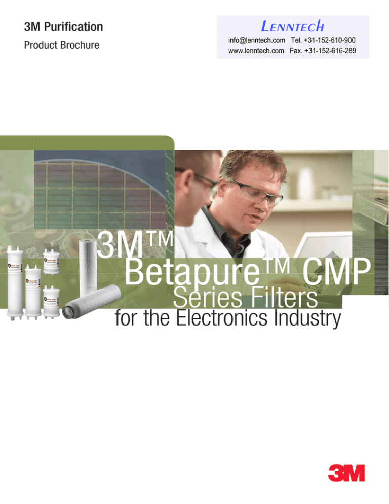
3M™
Betapure™ CMP
Series Filters
for the Electronics Industry
Superior reduction of large particle counts for improved yields
3M™ Betapure™ CMP filter cartridges and capsules, formerly known as CUNO
Optima CMP, are high capacity depth filters optimised for oxide and metal slurries
used in chemical mechanical planarisation (CMP) applications. Betapure CMP filters
are composed of all-polypropylene components and features a multi-zone “gradedporosity” design for the optimum level of particle classification. This construction
provides enhanced flow characteristics, including low pressure drop to minimise
shearing of the slurry while providing superior service life.
Graded porosity design
• Superior removal of hard and soft gel
contaminants, for reduced defectivity and
improved yields
• High contaminant holding capacity reduces
downtime and increases overall equipment
effectiveness
• The ilters are “matched” to the slurry
providing the optimum level of performance
needed to dramatically reduce defect
causing particles
• Provides a low pressure drop reducing the
potential for luid shear of the slurry
100% polypropylene construction
• Low capsule extractables, free of
adhesives, binders and surfactants
• Excellent chemical compatibility with low
and high pH slurries
Quality manufacturing
• ISO certiied quality management system
• Manufactured and double-bagged in a
clean environment to provide superior
downstream cleanliness out of the package
Built to exacting speciications
• Provides a consistent quality of slurry
enabling repeatability of the planarisation
process
Fully disposable capsule
• Rapid installation
• Reduced downtime
• Reduced handling of hazardous chemicals
3M Purification’s Betapure CMP filters reduce large particle counts that can
potentially reduce yields while maintaining the polishing characteristics of the slurry.
Particle size distribution
The filtration of CMP slurries is a challenging process as compared to the filtration
of high purity chemicals used in electronics manufacturing. High purity chemical
filtration is typically performed using 0.2 micron or tighter membrane filters that
have a sharp particle removal cut-off at the rated pore size. The majority of CMP
slurries contain a desired mean particle size that ranges from 0.03 to 0.2 microns.
Consequently, the filter that was specifically designed for particle clarification of
high purity chemicals would strip out the desired particles and adversely affect the
polishing characteristics of the CMP slurry. Oversized particles in the slurry typically
greater than 0.5 micron are undesired and represent the “tail” (figure 1) of the particle
size distribution (PSD). Betapure CMP filters remove the PSD tail while allowing the
majority of desired or “target” size particles to pass through it unchanged.
Applications
Semiconductor
• Oxide/low-k dielectrics
• Shallow Trench Isolation (STI)
• Interlevel Dielectric (ILD)
• Polysilicon
• Tungsten
• Copper
Data storage
• Magnetic heads
• Nickel and glass substrates
Data transmission
• Optical ibre
Compound semiconductor
• Light Emitting Diode (LED)
2
Figure 1
Particle Size Distribution > 0.5 micron
Colloidal-Silica Slurry & ISO Test Dust
200 000
Number of Particles per ml
Features and beneits
The objective of a slurry filter is for the majority of particles to pass through it
unchanged, while only removing the undesired or “oversized” particles. The oversized
particle population is commonly referred to as large particle counts (LPC) and they
typically form over time when the suspended particles in the slurry settle forming
aggregates, agglomerates and gels. Large particles can also be the result of adverse
shipping conditions, shearing, slurry drying and interaction with other distribution
loop components such as fittings, tanks, piping, valves and pumps. These large
particles can scratch metal and interlevel dielectrics potentially causing wafer defects.
Colloidal-Silica Slurry
150 000
100 000
ISO Test Dust
50 000
0
0.5
1
2
5
Particle Diameter (microns)
10
3M™ Betapure™
CMP Series
In figure 2, particle removal efficiency is compared for the same grade of CMP filters
from 3M Purification. The filters were challenged using both a laboratory test dust and
colloidal-silica slurry. There is a significant difference in particle removal efficiency,
which is a direct result of the contaminant PSD distribution. The broad PSD of the test
dust yields significantly higher particle removal efficiency than achieved when tested
with slurry. Therefore, test dust is not representative of slurry and ratings based on test
dust will likely be overstated and meaningless for CMP slurry applications.
In figure 3, particle removal efficiency is compared for equivalent rated CMP filters
from 3M Purification, Competitor A and Competitor B in colloidal-silica slurry. The
data clearly shows that equivalent rated filters from different manufacturers does not
deliver equivalent performance and reinforces the fact that the “rating” generated in a
lab using test dust is not meaningful in predicting actual performance. Based on this
information particle removal efficiency generated in slurry is the best measure of filter
performance. Other important factors in selecting the appropriate slurry filter include
particle classification, pressure drop and filter lifetime.
Figure 2: Particle removal eficiency
colloidal-silica vs. ISO test dust
100
3M™ Betapure™ CMP 560 - Colloidal-silica
3M™ Betapure™ CMP 560 - ISO test dust
Particle Removal Efficiency (%)
Figure 1 compares the PSD of colloidal-silica slurry and a laboratory test dust
which is typically used by filter suppliers to establish depth filter ratings. The data
shows that test dust has a broader PSD above 0.5 micron proving that it is not a
true representation of the types of particles in CMP slurry. A wide variation in
performance also exists from one filter supplier to the next because there is no
industry accepted standard for rating retention of depth filters. Furthermore, absolute
and nominal filter ratings are both used to specify particle removal efficiency which
only serves to confuse the situation while not providing the application specific
information needed.
80
60
40
20
0
Particle Size > 0.54 micron
Figure 3: Comparative particle removal
eficiency in colloidal-silica for equivalent
rated ilters
100
80
Particle Removal Efficiency (%)
Particle removal eficiency is the best measure of ilter performance
3M™ Betapure™ CMP
Competitor A
Competitor B
60
40
20
0
Particle Size > 0.54 micron
Superior particle retention through graded porosity design
The multiple higher porosity layers on the upstream section (figure 5) provide
effective prefiltration of oversized particles resulting in higher contaminant removal
capacity and increased filter lifetime. This graded porosity (figure 5) design also
provides a tortuous downstream path and low pressure drop which is ideal for gel
capture and reduced shear effect on the slurry.
Figure 4: Percent Solids Comparison Colloidal-Silica
0.5
Influent
Effluent
0.4
Percent Solids (%)
Betapure CMP filter media was specifically engineered to provide a low porosity,
downstream section with a sharp retention cut-off that closely aligns to the size
distribution of undesired particles to be removed. This sharp removal cut-off will
not alter percent solids (figure 4) or remove desired or “target” size particles thus
preserving the polishing characteristics of the slurry. In contrast, competitive point-ofuse filters (figure 4) that have a broad removal range can in fact retain particles smaller
than the PSD. Removing these “target” size particles can alter the percent solids of the
slurry which in turn reduces filter lifetime because more particles are being removed
than required in the application.
Particle Size > 1.01 micron
0.3
0.2
0.1
0
Competitor A
3M™ Betapure™ CMP
Figure 5: Graded Porosity Design
Proper iltration provides for reduced defectivity
Large particles, greater than 0.5 micron, can scratch metal and interlevel dielectrics
potentially causing wafer defects. Variations in particle size distribution and
particle counts in the slurry can affect repeat ability of the planarisation process.
In both cases, major reductions in large particle counts can be associated to proper
filtration, resulting in reduced defectivity (figure 6) and an increase to yields. Proper
filtration also provides a consistent quality of slurry which enables repeat ability
of the planarisation process. The ideal slurry filter will have a retention curve that
closely aligns to the PSD of “undesired” particles to be removed. By matching that
characteristic, Betapure CMP filters are able to maintain the polishing characteristics
of the slurry, maximise contaminant holding capacity and increase filter lifetime.
3
Filter Removal Eficiencies
Figure 6: Beneits of proper iltration
horizon capture of copper wafer surface
Depending on the location in the slurry distribution system a filter with a sharp
particle removal cut-off and a filter with a broad particle removal cut-off will
be needed to reduce defectivity and increase yields. For example, in single pass
applications at point-of-use the filter should have a sharp cut-off which is slightly
larger than the desired PSD. Figure 7 shows that Betapure CMP 510, CMP 520, CMP
530 and CMP 540 contain that sharp cut-off making it ideal for particle classification
at point-of-use.
No Filtration - High Level of Defectivity
504 000
18.4
nm
nm
0
However, in the distribution loop, the filter should have a broad removal range
that closely aligns to the undesired PSD tail to be removed like that exhibited by
Betapure CMP 550, CMP 560, CMP 570, CMP 580 and CMP590. Betapure CMP
filters for distribution loop applications contain a higher porosity media as compared
to Betapure CMP filters at point-of-use. The higher porosity media increases flow
while reducing pressure drop and fluid shear on the slurry. Increasing flow while
maintaining particle removal efficiency results in particle specifications being
achieved in less time. Figure 8, shows the particle removal efficiency of a Betapure
CMP 560 filter in re-circulation mode over specific time intervals.
0
0
nm
504 000
With Filtration - Relatively Defect Free
504 000
19.9
nm
nm
“Matching” the slurry to the proper Betapure CMP filter provides the peak level of
performance needed to dramatically reduce defect causing large particle counts. The
porosity of the media layers can also be customised to meet the specific requirements
of CMP slurry manufacturers.
0
0
0
nm
504 000
Betapure CMP ilter construction
Betapure CMP filters are constructed using all-polypropylene components (see table
1). Capsules are manufactured using the most advanced non-contact thermoplastic
welding techniques - no adhesives, binders or surfactants are used in the process and are double-bagged in a clean environment to ensure superior cleanliness out of
the package. The Betapure CMP filter manufacturing site operates within an ISO
certified quality management system.
Figure 7: Betapure CMP particle removal
eficiency
100
CMP 510
CMP 520
CMP 530
CMP 540
CMP 550
CMP 560
CMP 570
90
Particle Removal Efficiency (%)
80
70
Table 1: Product Specifications
Material of Construction
60
Filter Media and Media Support Layer
50
40
30
Capsule Housing & Filter Core and End Caps
polypropylene
Filter O-rings/Gaskets
see ordering guide
Dimensions
20
Length
see “Capsule Configurations” and “Cartridge
Configurations”
Outside Diameter
Capsule: 9.8 cm
Cartridge: 6.6 cm
10
0
0
0.2
0.4
0.6
0.8
1.0
1.2
1.4
Particle Size (microns)
Operating Conditions
Figure 8: Particle removal eficiency over
time
200 000
Maximum Operating Pressure
Capsule: 5.2 bar at 40 °C
Maximum Forward Differential Pressure
Capsule: 2.7 bar at 40 °C
Cartridge: 4.1 bar at 30 °C and 2.0 bar at 60 °C
Maximum Operating Temperature
Capsule: 40 °C
Cartridge: 60 °C
Number of Particles per ml
Inlet
150 000
10 minutes Outlet
Betapure CMP Filters Flow Rates
60 minutes Outlet
Figure 9 depicts typical 10” cartridge flow rates for 1 cP fluids at 20 °C.
100 000
120 minutes Outlet
180 minutes Outlet
50 000
0
0.5
1
Particle Diameter (microns)
4
polypropylene
2
Figures 10 through 13 depict typical flow rates of 1 cP fluids at 20 °C for 4”, 10”, 15”
and 20” capsules with 3/8” Flaretek® fittings. Consult 3M Purification or your local
3M Purification distributor for flow rate information about capsules with other end
connections.
3M™ Betapure™
CMP Series
CMP540,
CMP550 or
CMP560
Colloidal Silica Oxide
CMP560
CMP550, CMP560 or CMP570
CMP520,
CMP530 or
CMP540
0.6
53
0
CMP560, CMP570 or CMP580
0
P
CMP560
CM
Fumed Silica Oxide*
10
POU
Dispense (3)
520
Filtration Location (see Figure 13)
Distribution Loop (2)
CMP
5
Post
Blending (1)
P
54
50
P5
CM
CM
CMP
Slurry Type
Figure 9: 10” Cartridge low rate vs.
pressure drop for 1 cP luids at 20 °C
0.5
Differential Pressure (bar)
Table 2: Betapure CMP Filter Recommendation Guide
0.4
CMP
0.3
560
0
CMP 57
0.2
0.1
Silica Based Metal
CMP560
CMP560 or CMP570
CMP520,
CMP530 or
CMP540
CMP540 or
CMP550
CMP540 or CMP550
CMP510 or
CMP520
Non – Silica Based Metal
> 2% Solids
CMP560
CMP560 or CMP570
CMP530 or
CMP540
0
* Shear sensitive
Figure 14
Betapure CMP Particle Removal Eficiency
10
20
30
Fluid Flow Rate (l/min)
Figure 10: 4” Capsule* low rate vs.
pressure drop for 1 cP luids at 20 °C
0.6
Differential Pressure (bar)
Non - Silica Based Metal
< 2% Solids
CMP 580
CMP 590
0
0.5
0.4
Filter Grade
510/520
530
540
550
560
570
580
590
0.3
0.2
0.1
0
0
5
10
15
Fluid Flow Rate (l/min)
Figure 11: 10” Capsule* low rate vs.
pressure drop for 1 cP luids at 20 °C
Differential Pressure (bar)
0.6
0.5
0.4
0.3
Filter Grade
510/520
530
540
550
560
570
580/590
0.2
0.1
0
0
5
10
15
Fluid Flow Rate (l/min)
Betapure CMP Filter Grade
Typical Pore Size (Micron)
510
0.3
520
0.5
530
0.8
540
1
550
3
560
5
570
10
580
25
590
50
Figure 12: 15” Capsule* low rate vs.
pressure drop for 1cP luids at 20 °C
0.6
Differential Pressure (bar)
Table 3: Betapure CMP Filter to Pore Size Cross-Reference
0.5
0.4
0.3
Filter Grade
510/520
530
540
550
560
570
580/590
0.2
0.1
0
0
5
10
15
Fluid Flow Rate (l/min)
Figure 13: 20” Capsule* low rate vs.
pressure drop for 1 cP luids at 20 °C
3M Purification performs in-house and on-site filtration studies worldwide through
its Scientific Applications Support Services (SASS) group using the most advanced
particle counting technologies to optimise the CMP process at the customer facility. In
addition, 3M Purification works closely with the slurry manufacturers to characterise
and customise filtration solutions that meet current and future requirements.
Differential Pressure (bar)
0.6
SASS
0.5
0.4
0.3
Filter Grade
510/520
530
540
550
560
570
580/590
0.2
0.1
0
0
5
10
15
Fluid Flow Rate (l/min)
* with 3/8” Flaretek® itting
5
3M™ Betapure™ CMP Capsule
Conigurations
Capsule
Style
K
L
M
P
R
S
Length
Code
04
10
15
20
04
10
15
20
04
10
15
20
04
10
15
20
04
10
15
20
04
10
15
20
Dim. A
(cm)
14.07
29.31
42.01
54.71
14.07
29.31
42.01
54.71
14.07
29.31
42.01
54.71
14.07
29.31
42.01
54.71
14.07
29.31
42.01
54.71
14.07
29.31
42.01
54.71
Dim. B
(cm)
20.02
35.26
47.96
60.66
20.02
35.26
47.96
60.66
18.26
33.50
46.20
58.90
18.26
33.50
46.20
58.90
19.66
34.90
47.60
60.30
20.47
35.71
48.41
61.11
3M™ Betapure™ CMP Cartridge
Conigurations
Cartridge
Style
C
N
F
U
6
Length
Code
1 High
2 High
3 High
1 High
2 High
3 High
½ High
1 High
2 High
3 High
1 high
Dim. A
(cm)
32.5
57.2
82.3
24.9
49.8
74.7
13.2
27.9
52.6
77.7
26.4
Dim. B
(cm)
30.5
55.4
80.5
11.2
25.9
50.8
75.7
24.4
K Style
L Style
M Style
P Style
R Style
S Style
C Style
F Style
N Style
U Style
3M™ Betapure™
CMP Series
3M™ Betapure™ CMP ilter cartridge range - Ordering guide
Cartridge
CMP
Filter Grade
Media
Construction
Length
(Inches)
End Modiication
(see illustration on previous page)
510
P=
04 = 4 *
C = 222 O-ring & spear
520
polypropylene
cartridge
10 = 10
F = 222 O-ring & lat cap
20 = 20
U = 222 O-ring & lap cap **
530
540
Gasket / O-ring
Material
C = EPR
30 = 30
550
09 = 9
560
N = D.O.E. (double open end)
G = polyethylene
19 = 19
570
29 = 29
580
590
* F only
** Replaces Mykrolis Code 0, 10” length only (see U style on previous page)
3M™ Betapure™ CMP disposable ilter capsules range - Ordering guide
Capsule
Filter Grade
Media
Construction
CMP
510
C = Capsule
Length
(Inches)
04 = 4
End Connection
(see illustration on previous page)
K = 3/8” Flaretek®
®
520
10 = 10
L = 3/8” Flaretek with 1/4” Flaretek Vent and Drain
530
15 = 15
M = 1/4” MNPT
540
20 = 20
P = 1/4” MNPT with 1/4” MNPT Vent and Drain
550
R = 1/4” Flaretek® with 1/4” Flaretek Vent and Drain
560
S = 3/4” Flaretek® with 1/4” Flaretek Vent and Drain
Internal O-ring
Material
C = EPR
Packaging
01 = single
06 = 6-pack
570
580
590
NOTE: 3M™ Betapure™ CMP is new name for CUNO Optima CMP.
3M is a registered trademark of the 3M Company. Betapure is a registered trademark of the 3M Company used under license.
Flaretek is a registered trademark of Entegris, Inc.
7
Important Notice
The information described in this literature is accurate to the best of our knowledge. A variety of factors, however, can affect the performance of the Product(s) in a particular application, some
of which are uniquely within your knowledge and control. INFORMATION IS SUPPLIED UPON THE CONDITION THAT THE PERSONS RECEIVING THE SAME WILL MAKE THEIR OWN DETERMINATION
AS TO ITS SUITABILITY FOR THEIR USE. IN NO EVENT WILL 3M PURIFICATION BE RESPONSIBLE FOR DAMAGES OF ANY NATURE WHATSOEVER RESULTING FROM THE USE OF OR RELIANCE UPON
INFORMATION.
It is your responsibility to determine if additional testing or information is required and if this product is it for a particular purpose and suitable in your speciic application.
3M PURIFICATION MAKES NO REPRESENTATIONS OR WARRANTIES, EITHER EXPRESS OR IMPLIED INCLUDING WITHOUT LIMITATION ANY WARRANTIES OF MERCHANTABILITY, FITNESS FOR A
PARTICULAR PURPOSE OR OF ANY OTHER NATURE HEREUNDER WITH RESPECT TO INFORMATION OR THE PRODUCT TO WHICH INFORMATION REFERS.
Limitation of Liability
3M Puriication will not be liable for any loss or damage arising from the use of the Product(s), whether direct, indirect, special, incidental, or consequential, regardless of the legal theory asserted,
including warranty, contract, negligence or strict liability. Some states do not allow the exclusion or limitation of incidental or consequential damages, so the above limitation may not apply to you.
Lenntech
info@lenntech.com Tel. +31-152-610-900
www.lenntech.com Fax. +31-152-616-289
For more contact addresses visit our website www.3M.eu/puriication.
Data may be subject to change without further notice.
© 3M 2012. All rights reserved.
v.2 - DOC10105
LITCTBPCMP1.EU - 1211


