PART VII: MECHANICAL CONNECTIONS
advertisement
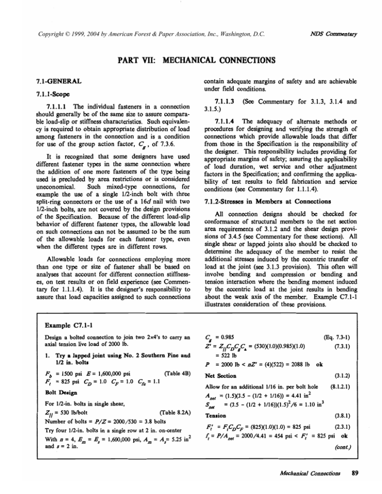
Copyright © 1999, 2004 by American Forest & Paper Association, Inc., Washington, D.C. ADS Commentary PART VII: MECHANICAL CONNECTIONS contain adequate margins of safety and are achievable under field conditions. 7.1-GENERAL 7.l.l-hpe 7.1.1.1 The individual fasteners in a connection should generally be of the same size to assure comparable load-slip or stiffness characteristics. Such equivalency is required to obtain appropriate distribution of load among fasteners in the connection and is a condition for use of the group action factor, Cg, of 7.3.6. It isrecognized that somedesignershave used different fastener types in the same connection where the addition of onemore fasteners ofthetypebeing used is precluded by area restrictions or is considered uneconomical. Such mixed-type connections, for example the use of a single1/2-inch bolt with three split-ring connectors or the use of a 16d nail with two 1/2-inch bolts, are not covered by the design provisions of the Specification. Because of the different load-slip behavior of different fastener types, the allowable load on such connections can not be assumed to be the sum of the allowable loadsfor each fastener type, even when the different types are in different rows. Allowable loadsfor connections employing more thanone type or sizeof fastener shall bebased on analyses that account for different connection stiffnesses, on test results or on field experience (see Commentary for 1.1.1.4). It is the designer’sresponsibility to assure that load capacities assigned to such connections 7.1.1.3 (See Commentary for 3.1.3, 3.1.4 and 3.1.5.) 7.1.1.4 The adequacy of alternate methods or procedures for designing and verifying the strength of connections whichprovideallowable loadsthat differ from those in the Specificationis the responsibility of the designer. This responsibilityincludesproviding for appropriate margins of safety; assuring the applicability of loadduration, wetservice andother adjustment factors in the Specification; and confiming the applicabilityoftest results to field fabricationand service conditions (see Commentary for 1.1.1.4). 7.1.2-Stresses in Members at Connections All connection designs should be checked for conformance of structural members to the netsection area requirements of 3.1.2 and the shear design provisions of3.4.5 (see Commentary for these sections). All single shear or lapped joints also should be checked to determine the adequacy of the member to resistthe additional stresses induced by the eccentric transfer of load at the joint (see 3.1.3provision). This often will involve bending and compression or bending and tension interaction where the bending moment induced by the eccentric load at the joint results inbending about the weak axis of the member.ExampleC7.1-1 illustrates consideration of these provisions. Example C7.1-1 Design a bolted connection to join two 2x4‘s to carryan axial tension live load of 2000 Ib. 1. Try a lapped joint using No. 2 Southern Pine and 1/2 in. bolts Fb = 1500 psi Fr = 825psi E = 1,600,000 (Table psi CD = 1.0 C ’ = 1 .O Cfu= 1.1 4B) Bolt Design For 1/2-in. bolts in single shear, Zll = 530 Ibholt 8.2A)(Table Number of bolts = P / Z = 2000/530 = 3.8 bolts Try four 1/2-in. bolts in a single row at 2 in. on-center 2 With n = 4, E, = E, = 1,600,000 psi, A, = As= 5.25 in and s = 2 in. (&. Cg = 0.985 2’= Z,/C’C,C, = (530X1.0)(0.985)(1 .O) = 522lb P = 2000 Ib c 02’= (4)(522) = 2088lb ok Net Section (3.1.2) Allow foranadditional1/16 in. per bolthole A,, = (15x33 - (112 + 1/16)) = 4.41in2 S,& = (3.5 - (1/2 + 1/16))(1.5)2/6 = 1.10in3 (8.1.2.1) Tension (3.8.1) F; = FrCDCF= (825)(1.0)(1.O) = 825 psi fr = P/Aner = 2000/4.41 7.3-1) (7.3.1) (2.3.1) = 454 psi < F; = 825psi ok (cod.) Mecbanid Connections 89 ) ADS Commentary Example C7.1-1 (cont.) Bending (3.3) Bending is induced about the weak axis due to the eccentricity of the lapped connection of 1.5 in. Fb* = Fbc,cKfu = (1500)( 1.O)( 1.O)( 1.1) = 1650 pSi(3.9.1) Since d c b (1.5 < 3.5 in.), CL = 1.O (3.3.3.1) Fb' = Fb**= FbcDcLcFcfu (3.9.1) = (1500)( 1.Ox 1.O)( 1.O)( 1.1) = 1650 psi fb = M/Snd = Pe/Snd = (2000)(1.5)/(1.10) = 2727 psi > F t = 1650psi ng Connection is not adequate for bending, try another design 2. Try a lapped joint using Select Structural Southern Pine and 1/2 in. bolts Fb = 2850 psi E = 1,800,000 (Table psi 4B) Fr = ld00 psi C, = 1.O CF = 1.0 Cfu= 1.1 3. To reduce the eccentricity of the connection, try a spliced joint using Select Structural Southern Pine with a single 5/16-in. steel plate and 1/2 in. bolts Bolt Design For 1/2-in. bolts in single shear with 916-h. side plate, Zll = 613 lb/bolt (Eq. 8.2-3) Number of bolts = P / Z = 2000/613 = 3.3 bolts Try four 1/2-in. bolts in a row on each side of splice at 2 in. on-center With n = 4, E, = 1,800,000 psi, E, = 30,000,000 psi, A, = 5.25 in2, A, = 1.094 in2 and s = 2 in. Cg = 0.949 2' = Z//CDCgCA= (613)( 1.0)(0.949)( 1.0) (7.3.1) = 582 lb P = 2000 lb c 02' = (4)(582) = 2328 lb ok a. 7.3-1) Bolt Design Tension As before, Zll = 530 lbholt (Table 8.2A) Try four 1/2-in. bolts in a single row at 2 in. on-center 2 With n = 4, E, = E, = 1,800,000 psi, A, = A, = 5.25 in and s = 2 in. (Eq. Cg = 0.987 2' = ZllCDCgCA= (530)( 1.0)(0.987)( 1 .O) (7.3.1) ok Tension (3.8.1) F; = FtC,CF = (1600)(1.0)(1.O) = 1600 psi (2.3.1) = P/Aner= 2000/4.41 = 454psi < F; = 1600psi ok ft Bending (3.3) Eccentricity = 1.5 in. Fb*= FbC,Cflfu = (2850)(1.0)(1.0)(1.1) = 3135 pSi(3.9.1) Fb' = Fb**=FbcDcLck% (3.9.1) = (2850)( .1O)( 1.O)( 1.O)( 1.1) = 3 135 psi fb = M/Sner= Pe/Sner= (2000)(1.5)/(1.10) = 2727 psi < F; = 3135 psi ok Combined Bending and fl -+- F; Axial Tension f6 -- 2727 454 F ~ * 3135 1600 F; = FrCDCF= (1600)(1.0)(1.0) = 1600 psi (2.3.1) = 454psi c F; = 1600psi ok ft = P/Aner= 2000/4.41 Bending = 523 lb = 2000 lb < nZ' = (4)(523) = 2092lb P - + - -- 1.15 > 1.0 (3.9.1) ng 90 Mxhanid Connections combined bending and (3.3) There is still bending induced about the weak axis; however the eccentricity is reduced to 1/2(1.5)+ 1/2(5/16)= 0.906in. F i = FbcDcfifu = (2850)(1.0)(1.0)(1.1) = 3135 pSi(3.9.1) Fi = Fb8*=FbcDcLck% (3.9.1) = (2850)( .1O)( 1.O)( 1.O)( 1.1) = 3 135 psi fb = M/Snd = Pe/Snd = (2000)(0.906)/(1 .lo) = 1648psi < F i = 3135psi ok Combined Bending and Axial Tension 454 1648 - +f ,- - f6 - + - = 0.81 1.0 1600 3135 F; F~* -f b- - fr Fi* (3.9.1) ok -454 = 0.38 < 1.0 ok 3 135 This connection is adequate,but requires 8 bolts. Try a double platddouble shear spliced connection to eliminate the eccentricity, reduce the number of bolts and allow for the use of a lower grade of lumber. 4. Try a spliced joint using No. 3 Southern Pine with two 1/8-in. steel plates and1/2 in. bolts Fb = 850 psi Ft = 475psi Connection is notadequatefor tension, try another design (3.8.1) E = 1,400,000 psi (Table 4B) CD = 1.0 CF = 1.0 Cf. = 1.1 (cont.) NDS Commentary ~~~ ~~ Example C7.1-1 (cont.) Bolt Design Bolt Design For 1/2-in. bolts in double shear with 1/8-in. side plates, For 1/2-in. bolts in double shear with two 1 x4 side plates, Zll = 1153 lbholt Try two 1/2-in. bolts in a row on each side of splice With n = 2, E, = 1,400,000 psi, E, = 30,000,000 psi A, = 5.25 in2, A, = 0.875 in 2 and s = 2 in. cg = 0.991 (Eq. 7.3-1) 2’ = Z#”CgCA = (1 153)( 1.0)(0.991)(1 .O) (7.3.1) = 1143 lb P = 2000 Ib < 02’ = (2)(1143) = 2286psi ok Zll = 1077 Ibholt 8.3-3) (Eq. Number of bolts = P/Z = 2000/1077 = 1.86 bolts Try two 1/2-in. bolts in a row on each side of splice With n = 2, E, = 1,400,000 psi, E, = 1,600,000 psi A, = 5.25 in 2, A, = 5.25 in 2 and s = 2 in. cg = 0.999 (Eq. 7.3-1) 2’ = Z/lCDCgCA = (1077)(1.0)(0.999)(1.0) (7.3.1) = 1076Ib P = 2000lb c 02’= (2)(1076) = 2152 Ib ok Tension Tension (Eq. 8.3-1) Number of bolts = P/Z = 2000/1153 = 1.73 bolts (3.8.1) F; = FfC’CF = (475)(1.0)( 1 .O) = 475psi (2.3.1) 4 = P/Anef= 2000/4.41 = 454psi < F; = 475psi ok Since the eccentricity of the connection has been eliminated thereis no bending.Theconnectiondesignsatisfies NDS provisions. 5. Try a spliced joint using No. 3 Southern Pine with two Industrial 45 (No. 2 stresses) Southern Pine 1x4 stress rated boards as side plates and 1/2 in. bolts (3.8.1) 1x4’s Anel = 2(0.75)(3.5 - (1/2 + 1/16)) = 4.41in2 F; = FfCDCF= (825)(1 .O)( 1 .O) = 825 psi (2.3.1) 4 = P/Anef= 2000/4.41 = 454psi c F: = 825psi ok 2x4‘s F: = FfC’CF = (475)(1 .O)( 1 .O) = 475psi (2.3.1) = 454psi < F: = 475psi ok 4 = P/Ane, = 2000/4.41 No. 3: N o eccentricity and therefore, no bending. The connection design satisfies N D S provisions. (SPIB Standard Grading Rules for Southern Pine Lumber) Connection designs 3, 4 and 5 all satisfy N D S provi4 or 5 probably being the most sions,withdesigns practical/economical. Ff = 475 psi E = 1,400,000 psi (Table 4B) C ’ = 1.0 CF = 1.0 Ind.45 (No. 2): Ff = 825psi E = 1,600,000psi 7.1.3-Eccentric Connections Avoidance of fastener eccentricity that induces tension perpendicular to grain stressesinthemain wood member at the connection was first introduced as a cautionary note in the 1944 edition of the Specification. Where multiple fasteners occurred with eccentricity, fasteners were to be placed, insofar as possible, such that the wood between them was placed in compression ratherthan intension (load coming into the joint through the right hand member and leavingthe joint through the left hand memberin Figure 7Aofthe Specification). The cautionary provisions on tension perpendicular to grain stresses at eccentric connections were dropped from the Specification in 1948 when new provisions for shear design of bendingmembers at connections were introduced. The present provision that eccentric connections that inducetensionperpendicular to grain stresses are not to be used unless it has been shown by analysis or test that such joints can safely carry all applied loads has been a part of the Specification since the 1982 edition. Becauseofbuildingcode requirements calling for designchecks for uplift or other load reversals, avoidance of tension perpendicular to gram stresses in configurations such as that shownin Figure 7Aoften is not possible. An alternative to this detail is to lap both web members on the same fastener axis or, where monoplane webs are required, to use steel straps attached to the ends of the webs to carry the loads to and from the chord member through the same bolt or pin. It is to be emphasized that no tension design values perpendicularto grain are givenin the Specification Mechaniid Connections 91 NDS Commentary (see Commentary for 3.8). This is because undetectable ring shake and checking and splitting that mayoccur as a result of drying inservice make it impractical to establish relihble, generally applicable design values for the property. The determination of the type and extentofthe analysis and/or testingrequired to demonstrate the adequacyofeccentric connections that inducetension perpendicular to grain stresses in the wood members is theresponsibilityof the designer. Use of stitch bolts or plates to resistsuchstresseswhenthey can not be avoided is a common practice. limitingwoodstressesusedin the yield model are based on the load at which the load-deformation curve from a fastener embedment test intersects a line represented by theinitial tangent modulus offset 5 percent of the fastener diameter (163). This nominal yield point is intermediate between the proportional limit and maximum loads for the material and for theconnection. Figure C7.2-1 graphically illustrates typical a load-deformation curve from a fastener embedment test. P5%- 7.2-DESIGN VALUES 7.2.1-Single Fastener Connections PreviousBasis. Designvalues for connectionsin the 1986 and earlier editions of theSpecification were based on generalized relationships established from tests of the various typesoffasteners.These relationships used compression parallel or perpendicular to the grain strength, or specific gravity, whichisrelativelyclosely correlated withclearwoodcompressionproperties, as the measure of the influence of wood quality on connection load-carrying capacity. Adjustment ofthese basic wood properties for fastener diameter, length and placement was based on the results of joint tests. 1991 Edition. Lateral load design values for doweltype fasteners (bolts, lag screws,woodscrews, nails and spikes) are based on ayieldlimitmodel which specifically accounts for the different waysthese connections can behave under load. These behavior patterns or modes (see Appendix I of the Specification) are uniform bearing in the wood under the fastener, rotation of the fastener in the joint without bending, and development of one or more plastic hinges in the fastener(93,167). Equations have beendeveloped for each mode relating the joint load to themaximum stressesin the woodmembers and in the fastener (93,166). The capacity of the connection under each yield mode iskeyed to the bearing strength of the wood under the fastener and the bending strength of the fastener, with the lowest capacity calculated for the various modes being taken as the design load for the connection. The yield limit model provides a consistent basis for establishing the relative effects of side and main memberthickness and bearing strength, and fastener bending strength on the load-carrying capacity of connections involving dowel type fasteners. Because the yield strength of a wood connection is not well defined on the load-deformation curve for a connection, the 92 Mechanid Connections 5% of diameter Deformation (in). FlgureC7.2-ITypicalload-defonnationcurve bendhg peld deslgnvalue hsteners. to detemhe for dowel t y p Lateral design loads for connections inprevious editions of the Specification represented nominal proportional limitvalues. For purposes of transition and to build on the long record of satisfactory performance obtained withthesepreviousvalues, short-term loads based on direct application of the yieldlimit equations havebeenreduced to the nominalaverage design load levelspublishedinprevious editions for connections made withequivalentspecies and member sizes. This was done by .establishing average ratios of previousSpecification loads to yield model loads for each mode of failure and direction of loading (parallel and perpendicular to grain). As noted under the commentaries for specific fastener types, this soft conversionprocedurebased on averagedesignload levels results in some new design loads for each fastener typebeinghigher and somelower than previous values depending upon the fastener diameter and the thickness of main and side menitMr. 7.2.2-Multiple Fastener Connections The allowabledesignvalue for aconnectioncontaining two or more fasteners is obtained by summing the allowable loads for eachindividual fastener. It is to be understood that thisprovisionrequiresapplication of the group action factor of 7.3.6 to the individu- A?DS Commentary a1 fastener design value wherever a row of two or more splitring connectors, shear plate connectors, bolts or lagscrews are involved. Summation of individual fastenerdesignvalues to obtain a total design value for a connection containing two or more fasteners islimited to designsinvolving the sametype and the same size of fastener (see Commentaryfor 7.1.1.1). Fasteners of the sametype, diameter and length joining the samemembers and resisting load in the same shear plane may be assumed toexhibit the sameyieldmode. 7.2.3-Design of Metal Parts Metal parts, including fasteners, are to bedesigned in accordance with national standards of practice and specifications applicable to the material. Tension stressesin fasteners as a result of withdrawal loads, shear in cross-sections of fasteners, bearing of fasteners on metal sideplates,tension and shear of plates, and buckling of plates and rods are included under this provision. Standard metal design practices are not to beused to account for bending stresses occurring in dowel type fasteners inwood connections subject to lateral loads. Thesestresses areaccountedfor inthisSpecification under the provisions for the particular fastener type involved. In allcaseswhere the designvalue for a connection involving metal fastenersisbased on the provisions of the Specification, the adjustment factors of7.3 are to be applied. Where the capacity of the connection is controlled by the strength of the metal fastener or part, the adjustment factors of7.3 arenot to beapplied. In thesecases, the design for such metal fasteners and parts arenotto beincreased1/3 for wind or earthquake loadings if the design load on the connection or part has been reduced for load combinations in accordance with the applicable buildingcode or national Load combinations which in the standard (10). probability of simultaneous occurrence is reflected in a reduced total design load generally will include dead load pluslive load pluswind load or dead load plus live load plus earthquake load (see Commentary 2.3.2.3). 7.3-ADJUSTMENT OF DESIGN VALUES 7.3.1-Applicability of Adjustment Factors Table 7.3.1 indicates what adjustment factors apply to connector designvaluesbased on the type of load on the connection: 2,P and Q refer to lateral loads; W refers to withdrawal loads. Design values for all fastener types are adjusted for load duration, wet service and temperature except values for toe-nails loaded in withdrawal are not modified for wet service. Adjustments for multiple fasteners in a row, Cg, applyonly to laterallyloaded bolts, lag screws, shear plates, split rings, drift pins and drift bolts. The geometry factors, CA, refertoend and edge distance and spacingrequirements for these same fasteners andfor laterally loaded spikegrids. Diaphragm and toe-nail adjustment factors are limited to nail and spikesonly. Specificdesignprovisions for drift bolts, drift pins and spikegrids are not givenin the Specification. Other authoritative sources for thedesignofconnections with these fastener types should be consulted (see Part XIV of the Specification). The metal side plate adjustment factor, C't , cited in the footnote of Table 7.3.1 refers to the modlfication of design values for shear plate connectors when metal rather than woodsideplates are used(see10.2.4of Specification). 7.3.2-Load Duration Factor, CD The impact load duration factor of 2.0 is not to be applied to design loads for connections. This new equalimitation is a resultof the use ofyieldmodel tions to establish the capacities of laterallyloaded connections made with dowel type fasteners. These equations take into account the bending yield strength of the metal fasteners, a property whichinfluencesthe design load of the connection in many configurations. As load duration adjustments for woodproperties are not applicable to metal properties, increases in connector lateral design loads where impact loading conditions occur is not appropriate. Lateral connector loads based on the procedures of the Specificationmay be increased for other load durations, includingthe1.6 modification for wind andearthquake loads, because the reduction factors used to adjust yieldmodelvalues (10 minute duration) to normal load design levels include a U1.6 component. Extension of the 1.6 maximum duration of load adjustment limit to connections made withnon-dowel type fasteners and to those where the fastener is subject to withdrawal loads has been madefor purposes of uniformity and inrecognition that design loads for these other connections also are derived from the results of standard short-term tests (5-10 minute duration) rather than impacttests. Mechanil'cal Connections 93 A?DS Comentary 7.3.3-Wet Service Factor, CM Applications representing dry conditions of use are discussedin the Commentary for 2.3.3. The wet service factors in Table 7.3.3 for bolts and lag screws, split ring and shear plate connectors, wood screws and common nails have been provisions of the Specificationsince the 1944 edition. The factor for threaded, hardened nailswas added in1962.These adjustments wererecommended as part of the early research on wood connections (57,62). The factors for metal connector plates were added in 1968. The 0.80 factor for plates installed in partially seasoned or wet lumber is based on the results of both truss and tensionin-line joint tests(1,150,195). The factors for drift pinswere added in1977. The factor of0.40 in the footnote of Table 7.3.3 for multiplerowsof bolts or lagscrewsinstalledin partiallyseasonedwoodusedin dry conditions of service has been a provisionoftheSpecificationsince 1948. In earlier editions, this factor was 1/3. The adjustment isbased on limitedtests of connections fabricated withunseasonedmembers joined at right angles to each other and tested after drying (62). 7.3.4-Temperature Factor, Cr The temperature adjustment factors for connections in Table 7.3.4 are equivalent to those for bending, compression and shear design values in 2.3.4 (see Commentary for thissection).Bearing under metal fasteners is closely correlated with compression parallel to grain or compression perpendicular to grain properties. 7.3.5-Fire Retardant Treatment (See Commentary for 2.3.6.) 7.3.6-GroupActionFactor, Cg Background Modification factors for two or more splitring connectors, shear plate connectors, bolts or lagscrews in a rowwere added to the Specificationin the 1973 edition. Earlier tests of bolted and shear plate connector joints had shown that the load capacity of connections containing multiple fasteners in a rowwas not directly proportional to the number offasteners,with those located near the ends of the row carrying a greater proportion of the applied load than those locatedin the interior of the row(46,48,50,92,100). 94 Mechanid Connectzons The tablesof factors includedin the 1973edition to account for the nonuniform loads on a rowof fasteners wasbased on a linear analysiswhereinthe directstressesin the main and sidemembers ofthe connection were assumed to be uniformly distributed across their cross section, and the relationship between fastener slip and fastener load was assumed to be linear (103). This analytical procedure showed that the transfer of load from side to mainmembers and the proportion of the total load carried by eachfastener were determined by the modulii of elasticity ( E ) and cross sectional areas of the side and main members, the number of fasteners in a row, the spacingbetween fasteners, and the joint load/slip modulus. Twotables of modification factors for joints containing two or more fasteners in a row were developed usingthe linear analysis: one for connectionswith woodsideplates and one for connectionswithmetal sideplates. For purposes of simplicity, factors were tabulated onlyintermsof the number offasteners in therow and thecrosssectional areas of themembers being joined. Other variables wereassumedtohave the followingvalues(201): Wood to woodconnections: E of side and main members Load/slip fastener modulus Spacingbetween fasteners 1,800,000psi 220,000Ib/in. 6.5 inches Wood to metal connections: E of main member Load/slip fastener modulus Spacingbetween fasteners 1,400,000psi 330,000Ibhn. 5.75inches With the foregoing constant values,theanalytical procedure was used to calculate modification factors for 3 to 8 fasteners in a row and then results were extrapolated up to 12 fasteners and down to 2 fasteners in a row (201). The resultingtablesof factors, ranging from 1.00 for two fasteners in a row to as low as 0.34 and 0.15 for 12 fasteners in a row in joints made with wood and metal side plates respectively, were continued essentiallyunchanged through the 1986 edition. 1991 Edition. The group action factor equation given 7.3.6 in is a newly developed consolidated expression for the analytical procedure used to establish the modification factors given in previous editions (234). Concurrent with the development of the compact single equation for accounting for group action, more recent load-slip data for bolted joints and split ring and shear plate connectors have been used to establish new representative load-slip modulii for differenttypes of ADS Commentmy The foregoing comparisons show that the group action factors for wood side plate connections tabulated in the 1991 edition for 1-inch boltsand lag screws 4-inch split ring or shear 500,000 Ib/in. (Table 7.3.6A) are slightly larger than those applicable plate connectors to these connections inprevious editions. For smaller diameter boltsand smaller spacings, the differences 2.5-inch split ring or 2.625-inch 400,000 Ib/in. would be larger. Alternatively, group action factors shear plate connectors or tabulated in the 1991 editionfor 4-inchsplitring shear plate connectors (Table 7.3.6B) are significantly Bolts or lag screws: lower than those applicable to these connections in wood to wood connection 180,000 (D"s) previous editions. This is primarily a result of the wood to metal connections 270,000 (Dl.') larger load/slip modulus assigned to this size connector relative to the average modulus assigned all connectors where: D = diameter, inches inprevious editions. Differences between group action factorstabulated in the 1991 edition and previous The foregoing modulii for 4-inch connectors and editions would be less for connections made with 1-inch diameter bolts or lag screws were used to smaller split ring or shear plate connectors and smaller develop the group action factors given in Tables spacings. 7.3.6A-7.3.6D. Factors for connections involving wood side plates (Tables A and B)were developed assuming Differences between tabulated group action factors an E of 1,400,000 psi for both main and side members in the 1991 edition and previous editions for connecand a spacing of 4 inches forbolts or lag screws tions made with metal side plates are similar to those (Table A) and 9 inches for connectors (Table B). The for connections made withwoodsideplates. This is effects of assuming different properties and spacings illustrated by the comparisons shown in Table C7.3-2. than those used previously to develop tabulated group action factors for connections with wood side plates is Effect of JointProperties. As indicated in the illustrated by the selected comparisons shown in Table footnotesto Tables 7.3.6A and 7.3.6B, group action C7.3-1. connections (234). These new joint stiffness parameters are: I Table C7.3-1 - Comparison of Group Action Factors for Connections made with Wood Side Plates Previous 1991 editions edition 1,800,000 1,400,000 Loadlslip modulus: Table C7.3-2 - Comparison of Group Action Factors for Connections made with Steel SidePlates Previous 1991 editions edition 1,400,000 30,000,000 1,400,000 30,000,000 Basis Em E, Load/slip modulus: 1-inch bolts or lag screws 4-inch connectors 220,000 220,000 180,000 500,000 1-inch bolts or lag screws 4-inch connectors 330,000 330,000 270,000 500,000 4.0 9.0 Spacing: 1-inch bolts or lag screws 4-inch connectors 5.75 5.75 4.0 9 .o n= 4 n = 12 n= 4 n = 12 0.90 0.49 0.98 0.81 0.94 0.59 0.99 0.88 n= 4 n = 12 n= 4 n = 12 0.90 0.49 0.98 0.81 0.82 0.35 0.96 0.66 Spacing: 1-inch bolts or lag screws 4-inch connectors 6.5 6.5 A c b Factot 1-inch bolts or lag screws: A, = 5 , A, = 10: A, = 64, Am = 64: - 4-inch connectors: A, = 5, A, = 10: A, = 64, Am = 64: n= 4 0.84 n = 12 0.38 n = 4 0.99 n = 12 0.88 0.78 0.32 0.99 0.82 n= 4 0.59 n = 12 0.20 n= 4 0.95 n = 12 0.58 0.78 0.32 0.99 0.82 1-inch bolts or lag screws: A, = 2, A, = 2 4 A, = 5, A , = 120: 4-inch connectors: A, = 2, A, = 24: A, = 5, A, = 120: ADS Comme0t.y factors for connections made withmembershaving E values greater than 1,400,OOO psi,spacingslessthan 4 inches, fasteners less than 1-inch in diameter and connectorsless than 4-inchindiameterwillbehigher than the tabulated factors. The sensitivity of the group action factor to changes in these variables isshownin Table C7.3-3. As shown in the Table C7.3-3, changes in E of the joint members,spacing and connector sizeresultin changes to group action factors of less than 20 percent. These tables may beused to help determine when the general equation of 7.3.6.1 should be used rather than Tables 7.3.6A - 7.3.61) to assign group action factors for specific designs. Table C7.3-3 - Effect of Joint Properties on Group Action Factors Wood SidePlates: Am = 10, As = 5 No. of E x lo6 boltsmainside 1.8 5 Grow Action Factor 1-inch bolt 1/2-inch bolt lodslip = 180,000 lodslip = 63,640 s= 4 s= 6 s= 4 s= 2 1.8 1.4 1.0 1.8 1.4 1.4 1.0 0.79 0.73 0.75 0.70 0.73 0.67 0.69 0.64 0.90 0.87 0.88 0.85 0.95 0.93 0.94 0.91 1.8 1.4 1.0 1.8 1.4 1.4 1.0 0.49 0.43 0.45 0.40 0.43 0.37 0.39 0.35 0.68 0.62 0.64 0.57 0.80 0.74 0.76 0.70 1.8 10 Steel Side Plates: No. of E x lo6 boltsmainside Am = 24, As = 2 Group Action Factor 1-inch bolt 1/2-inch bolt lodslip = 270,000 lodslip = 95,459 s= 4 s= 6 s= 4 s=2 1.8 5 30.0 1.4 30.0 1.0 30.0 0.93 0.90 0.85 0.90 0.86 0.80 0.97 0.96 0.94 0.99 0.98 0.97 10 1.8 30.0 1.4 30.0 1.0 30.0 0.74 0.67 0.58 0.67 0.60 0.51 0.87 0.83 0.77 0.93 0.91 0.86 It is to be noted that the variable As in the group action equation (7.3-1) represents the sum of the crosssectional area of the side members. Thus the equation accounts for single shear as well as double shear connections. For a connection with four or more 96 M=.anid Connections members,each shear planeisevaluated as a single shear connection(see 8.4). Wheresuch a connection contains two or more fastenersin a row, a group action factor is calculated for each shear plane using an As basedonthethinnestmemberadjacenttothe planebeingconsidered. Themodulus ofelasticityvalues to beusedwith equation 7.3-1, and which are the basis for the factors in Tables 7.3.6A - 7.3.61), are thedesign E values giveninTables 4 and 5 of the Supplement and Table 6A. Perpendicular to Grain Loading. Connections involving perpendicular to grain loading, such as joints betweenweb andchord members,generally do not involverowsof bolts containing largenumbers of fasteners in a rowperpendicular to grain.Similarly, large beams are generally supported on hangers rather than on stacked fasteners aligned perpendicular to grain in order to avoid splitting that can occur as a result of drying inlowrelativehumidityserviceconditions. Group action factors are limited by themaximum loads ontheendfasteners in a rowwithoutany adjustment for the redistribution of load to other more lightlyloadedfastenersintherow that isknownto occur as a result of yielding under load. Such redistribution isconsidered to besignificantwherefasteners load the member perpendicular to the grain because of therelativelylowstiffnessofwoodinthisdirection. Based on the infrequent use of more than two bolts or other fasteners in a row perpendicular to grain, and the redistribution of load that occurs between fasteners insuchconnections, it is standard practice to usethe same group action factor for rows of fasteners aligned perpendicular to grain as that for fastenersaligned parallel to grain. This procedure, which has been satisfactorilyusedsince 1973whenthe group action factor was first introduced, is continued in the current Specification. 7.3.6.2 The criteria for determining when staggered fasteners are considered to represent a single row have been part of the Specification since 1977. 7.3.6.3 The useofgrosssection areas and the definitionofcross-sectional area for fastenergroups loadedperpendicular to the grain were introduced in the 1973 edition at the time group action modifications were added to theSpecification. -
