Version 4.20 Algorithm New Retrievals from AIM/CIPS
advertisement

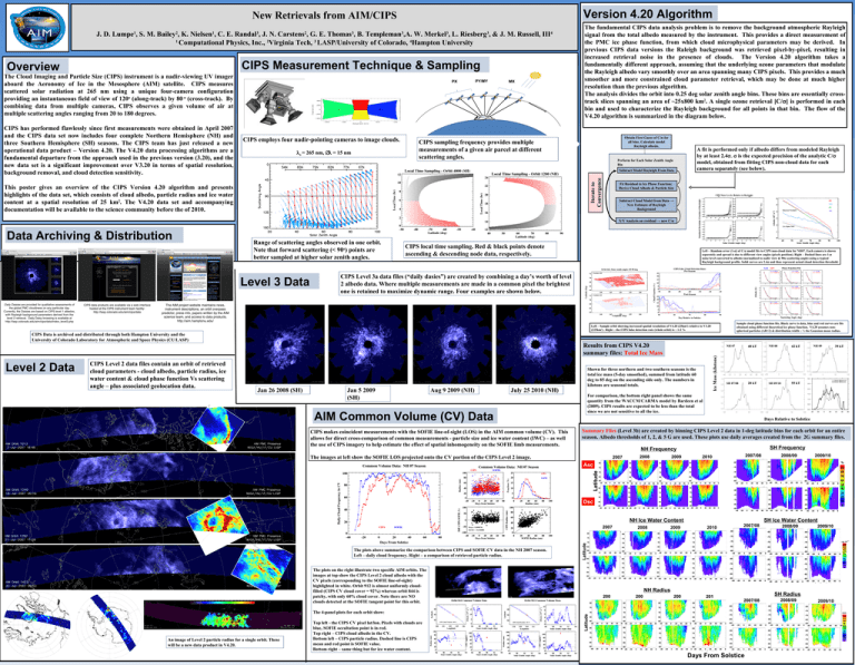
Version 4.20 Algorithm New Retrievals from AIM/CIPS J. D. Lumpe1, S. M. Bailey2, K. Nielsen1, C. E. Randal3, J. N. Carstens2, G. E. Thomas3, B. Templeman3,A. W. Merkel3, L. Riesberg3, & J. M. Russell, III4 1 Computational Physics, Inc., 2Virginia Tech, 3 LASP/University of Colorado, 4Hampton University CIPS Measurement Technique & Sampling The Cloud Imaging and Particle Size (CIPS) instrument is a nadir-viewing UV imager aboard the Aeronomy of Ice in the Mesosphere (AIM) satellite. CIPS measures scattered solar radiation at 265 nm using a unique four-camera configuration providing an instantaneous field of view of 120o (along-track) by 80 o (cross-track). By combining data from multiple cameras, CIPS observes a given volume of air at multiple scattering angles ranging from 20 to 180 degrees. CIPS has performed flawlessly since first measurements were obtained in April 2007 and the CIPS data set now includes four complete Northern Hemisphere (NH) and three Southern Hemisphere (SH) seasons. The CIPS team has just released a new operational data product – Version 4.20. The V4.20 data processing algorithms are a fundamental departure from the approach used in the previous version (3.20), and the new data set is a significant improvement over V3.20 in terms of spatial resolution, background removal, and cloud detection sensitivity. PX CIPS employs four nadir-pointing cameras to image clouds. λo = 265 nm, ∆λ = 15 nm PY/MY MX Obtain First Guess of C/σ for all bins. Calculate model Rayleigh albedo. CIPS sampling frequency provides multiple measurements of a given air parcel at different scattering angles. h A fit is performed only if albedo differs from modeled Rayleigh by at least 2.4σ. σ is the expected precision of the analytic C/σ model, obtained from fitting CIPS non-cloud data for each camera separately (see below). Perform for Each Solar Zenith Angle Bin Subtract Model Rayleigh From Data Iterate to Convergence Overview The fundamental CIPS data analysis problem is to remove the background atmospheric Rayleigh signal from the total albedo measured by the instrument. This provides a direct measurement of the PMC ice phase function, from which cloud microphysical parameters may be derived. In previous CIPS data versions the Raleigh background was retrieved pixel-by-pixel, resulting in increased retrieval noise in the presence of clouds. The Version 4.20 algorithm takes a fundamentally different approach, assuming that the underlying ozone parameters that modulate the Rayleigh albedo vary smoothly over an area spanning many CIPS pixels. This provides a much smoother and more constrained cloud parameter retrieval, which may be done at much higher resolution than the previous algorithm. The analysis divides the orbit into 0.25 deg solar zenith angle bins. These bins are essentially crosstrack slices spanning an area of ~25x800 km2. A single ozone retrieval [C/σ] is performed in each bin and used to characterize the Rayleigh background for all points in that bin. The flow of the V4.20 algorithm is summarized in the diagram below. This poster gives an overview of the CIPS Version 4.20 algorithm and presents highlights of the data set, which consists of cloud albedo, particle radius and ice water content at a spatial resolution of 25 km2. The V4.20 data set and accompanying documentation will be available to the science community before the of 2010. Fit Residual to Ice Phase Function; Derive Cloud Albedo & Particle Size Subtract Cloud Model from Data → New Estimate of Rayleigh Background X/Y Analysis on residual → new C/σ Data Archiving & Distribution Range of scattering angles observed in one orbit. Note that forward scattering (< 90o) points are better sampled at higher solar zenith angles. Level 3 Data CIPS local time sampling. Red & black points denote ascending & descending node data, respectively. Left – Random error (1-σ) of C/σ model fits to CIPS non-cloud data for NH07. Each camera is shown separately and spread is due to different view angles (pixels position). Right – Dashed lines are 1-σ noise level converted to albedo (normalized to nadir view & 90o scattering angle) using a typical Rayleigh background profile. Solid curves are 2.4σ and thus represent actual cloud detection threshold. CIPS Level 3a data files (“daily dasies”) are created by combining a day’s worth of level 2 albedo data. Where multiple measurements are made in a common pixel the brightest one is retained to maximize dynamic range. Four examples are shown below. Sample cloud phase function fits. Black curve is data, blue and red curves are fits obtained using different theoretical ice phase function. V4.20 assumes nonspherical particles (AR=2) & distribution width ~ ½ the Gaussian mean radius. Left – Sample orbit showing increased spatial resolution of V4.20 (25km2) relative to V3.20 (225km2) . Right – the CIPS false detection rate (whole orbit) is ~ 1-2 % CIPS Data is archived and distributed through both Hampton University and the University of Colorado Laboratory for Atmospheric and Space Physics (CU/LASP) Jan 5 2009 (SH) Aug 9 2009 (NH) July 25 2010 (NH) 40 kT NH 08 42 kT SH 07/08 20 kT SH 09/10 55 kT NH 09 Days Relative to Solstice Summary Files (Level 3b) are created by binning CIPS Level 2 data in 1-deg latitude bins for each orbit for an entire season. Albedo thresholds of 1, 2, & 5 G are used. These plots use daily averages created from the 2G summary files. SH Frequency NH Frequency The images at left show the SOFIE LOS projected onto the CV portion of the CIPS Level 2 image. 2007 2008 2009 2007/08 2010 2008/09 2009/10 Latitude Asc Dsc NH Ice Water Content The plots on the right illustrate two specific AIM orbits. The images at top show the CIPS Level 2 cloud albedo with the CV pixels (corresponding to the SOFIE line-of-sight) highlighted in white. Orbit 912 is almost uniformly cloudfilled (CIPS CV cloud cover = 92%) whereas orbit 844 is patchy, with only 60% cloud cover. Note there are NO clouds detected at the SOFIE tangent point for this orbit. The 4-panel plots for each orbit show: An image of Level 2 particle radius for a single orbit. These will be a new data product in V4.20. Top left - the CIPS CV pixel lat/lon. Pixels with clouds are blue, SOFIE occultation point is in red. Top right – CIPS cloud albedo in the CV. Bottom left – CIPS particle radius. Dashed line is CIPS mean and red point is SOFIE value. Bottom right – same thing but for ice water content. 2008 2009 2010 2007/08 SH Ice Water Content 2008/09 2009/10 Latitude 2007 The plots above summarize the comparison between CIPS and SOFIE CV data in the NH 2007 season. Left – daily cloud frequency. Right – a comparison of retrieved particle radius. 39 kT For comparison, the bottom right panel shows the same quantity from the WACCM/CARMA model by Bardeen et al (2009). CIPS results are expected to be less than the total since we are not sensitive to all the ice. AIM Common Volume (CV) Data CIPS makes coincident measurements with the SOFIE line-of-sight (LOS) in the AIM common volume (CV). This allows for direct cross-comparison of common measurements - particle size and ice water content (IWC) – as well the use of CIPS imagery to help estimate the effect of spatial inhomogeneity on the SOFIE limb measurements. Ice Mass (kilotons) Jan 26 2008 (SH) Shown for three northern and two southern seasons is the total ice mass (5-day smoothed), summed from latitude 60 deg to 85 deg on the ascending side only. The numbers in kilotons are seasonal totals. NH 07 NH Radius 200 200 200 CIPS Level 4 summary data for the Northern 7 8 9 Hemisphere 2007 season. This data is binned in 1degree latitude bins. 201 0 SH Radius 2007/08 Latitude Level 2 Data CIPS Level 2 data files contain an orbit of retrieved cloud parameters - cloud albedo, particle radius, ice water content & cloud phase function Vs scattering angle – plus associated geolocation data. Results from CIPS V4.20 summary files: Total Ice Mass Days From Solstice 2008/09 2009/10


