2- PELTON TURBINE:
advertisement
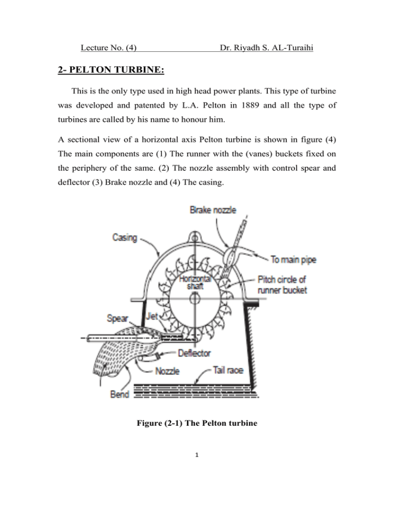
Lecture No. (4) Dr. Riyadh S. AL-Turaihi 2- PELTON TURBINE: This is the only type used in high head power plants. This type of turbine was developed and patented by L.A. Pelton in 1889 and all the type of turbines are called by his name to honour him. A sectional view of a horizontal axis Pelton turbine is shown in figure (4) The main components are (1) The runner with the (vanes) buckets fixed on the periphery of the same. (2) The nozzle assembly with control spear and deflector (3) Brake nozzle and (4) The casing. Figure (2-1) The Pelton turbine 1 Lecture No. (4) Dr. Riyadh S. AL-Turaihi The rotor or runner consists of a circular disc, fixed on suitable shaft, made of cast or forged steel. Buckets are fixed on the periphery of the disc. The spacing of the buckets is decided by the runner diameter and jet diameter and is generally more than 15 in number. These buckets in small sizes may be cast integral with the runner. In larger sizes it is bolted to the runner disc. The buckets are also made of special materials and the surfaces are well polished. A view of a bucket is shown in figure (5) with relative dimensions indicated in the figure. Originally spherical buckets were used and pelton modified the buckets to the present shape. It is formed in the shape of two half ellipsoids with a splilter connecting the two. A cut is made in the lip to facilitate all the water in the jet to usefully impinge on the buckets. This avoids interference of the incoming bucket on the jet impinging on the previous bucket. Equations are available to calculate the number of buckets on a wheel. The number of buckets, Z, Z = (D/2d) + 15 Where D is the runner diameter and d is the jet diameter. Figure (2-2) The Pelton turbine bucket 2 Lecture No. (4) Dr. Riyadh S. AL-Turaihi The head is generally constant and the jet velocity is thus constant. A fixed ratio between the jet velocity and runner peripheral velocity is to be maintained for best efficiency. The nozzle is designed to satisfy the need. But the load on the turbine will often fluctuate and sometimes sudden changes in load can take place due to electrical circuit tripping. The velocity of the jet should not be changed to meet the load fluctuation due to frequency requirements. The quantity of water flow only should be changed to meet the load fluctuation. A governor moves to and fro a suitably shaped spear placed inside the nozzle assembly in order to change the flow rate at the same time maintaining a compact circular jet. When load drops suddenly, the water flow should not be stopped suddenly. Such a sudden action will cause a high pressure wave in the penstock pipes that may cause damage to the system. To avoid this a deflector as shown in figure (6) is used to suddenly play out and deflect the jet so that the jet bypasses the buckets. Meanwhile the spear will move at the safe rate and close the nozzle and stop the flow. The deflector will than move to the initial position. Even when the flow is cut off, it will take a long time for the runner to come to rest due to the high inertia. To avoid this a braking jet is used which directs a jet in the opposite direction and stops the rotation. The spear assembly with the deflector is shown in figure (6). Some other methods like auxiliary waste nozzle and tilting nozzle are also used for speed regulation. The first wastes water and the second are mechanically complex. Inside the casing the pressure is atmospheric and hence no need to design the casing for pressure. It mainly serves the purpose of providing a cover and deflecting the water downwards. The casing is cast in two halves 3 Lecture No. (4) Dr. Riyadh S. AL-Turaihi for case of assembly. The casing also supports the bearing and as such should be sturdy enough to take up the load. When the condition is such that the specific speed indicates more than one jet, a vertical shaft system will be adopted. In this case the shaft is vertical and a horizontal nozzle ring with several nozzles is used. The jets in this case should not interfere with each other. Figure (2-3) Nozzle assembly Generally the turbine directly drives the generator. The speed of the turbine is governed by the frequency of AC. Power used in the region. The product of the pairs of poles used in the generator and the speed in rps gives the number of cycles per second. Steam turbines operate at 3000 rpm or 50 4 Lecture No. (4) Dr. Riyadh S. AL-Turaihi rps in the areas where the AC frequency is 50 cycles per second. Hydraulic turbines handle heavier fluid and hence cannot run at such speeds. In many cases the speed in the range to 500 rpm. As the water flows out on both sides equally axial thrust is minimal and heavy thrust bearing is not required. 5
