Solution: 23.45 kg/s. The volume flow rate is Q ... is (230 N/s)/(9.81 m/s )
advertisement
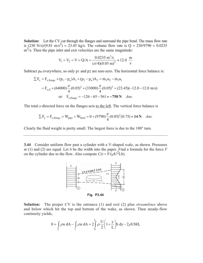
Solution: Let the CV cut through the flanges and surround the pipe bend. The mass flow rate is (230 N/s)/(9.81 m/s2) 23.45 kg/s. The volume flow rate is Q 230/9790 0.0235 m3/s. Then the pipe inlet and exit velocities are the same magnitude: V1 V2 V Q/A 0.0235 m3/s m | 12.0 2 s (S /4)(0.05 m) Subtract pa everywhere, so only p1 and p2 are non-zero. The horizontal force balance is: ¦ Fx 2 u2 m 1u1 m Fx,flange (p1 pa )A1 (p2 pa )A2 Fx,fl (64000) S (0.05)2 (33000) 4 or: Fx,flange S (0.05)2 (23.45)(12.0 12.0 m/s) 4 126 65 561 | 750 N Ans. The total x-directed force on the flanges acts to the left. The vertical force balance is ¦ Fy Fy,flange Wpipe Wfluid 0 (9790) S 4 (0.05)2 (0.75) | 14 N Ans. Clearly the fluid weight is pretty small. The largest force is due to the 180° turn. 3.44 Consider uniform flow past a cylinder with a V-shaped wake, as shown. Pressures at (1) and (2) are equal. Let b be the width into the paper. Find a formula for the force F on the cylinder due to the flow. Also compute CD F/(UU2Lb). Fig. P3.44 Solution: The proper CV is the entrance (1) and exit (2) plus streamlines above and below which hit the top and bottom of the wake, as shown. Then steady-flow continuity yields, 0 ³ 2 L U u dA ³ U u dA 2³ U 1 0 U§ y· ¨ 1 ¸ b dy 2 U UbH, 2 © L¹ Chapter 3 x Integral Relations for a Control Volume 205 where 2H is the inlet height. Solve for H 3L/4. Now the linear momentum relation is used. Note that the drag force F is to the right (force of the fluid on the body) thus the force F of the body on fluid is to the left. We obtain, ¦ Fx 0 ³ 2 uU u dA ³ uU u dA Use H 1 3L , then Fdrag 4 L 2³ 0 U§ y· U§ y· 2 ¨ 1 ¸ U ¨ 1 ¸ b dy 2HU U b 2 © L¹ 2 © L¹ 3 7 1 U U 2 Lb U U 2 Lb | U U 2 Lb 3 2 6 The dimensionless force, or drag coefficient F/(UU2Lb), equals CD Ans. 1/3. Ans. Fdrag
