WIRING INSTRUCTIONS 120 OR 277V TAP CONNECTION; 12 or 24V INSTALLATION PROCEDURES
advertisement
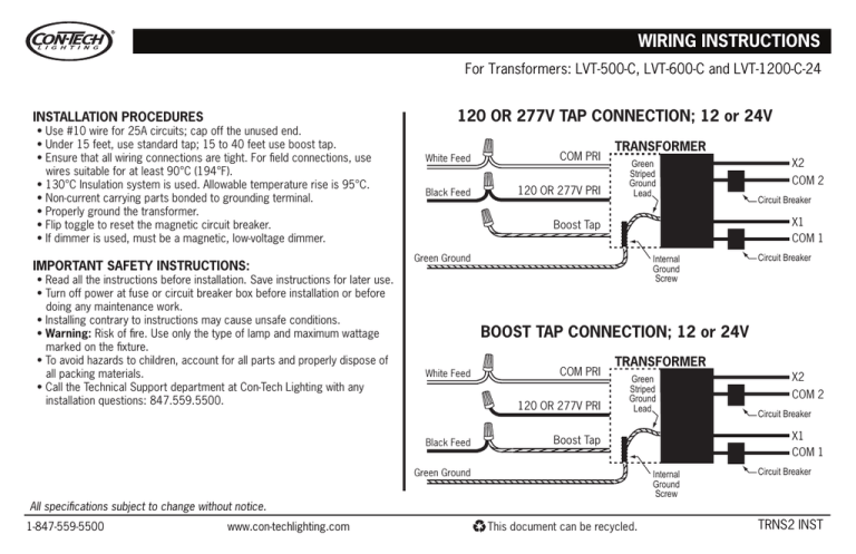
WIRING INSTRUCTIONS For Transformers: LVT-500-C, LVT-600-C and LVT-1200-C-24 INSTALLATION PROCEDURES • Use #10 wire for 25A circuits; cap off the unused end. • Under 15 feet, use standard tap; 15 to 40 feet use boost tap. • Ensure that all wiring connections are tight. For field connections, use wires suitable for at least 90°C (194°F). • 130°C Insulation system is used. Allowable temperature rise is 95°C. • Non-current carrying parts bonded to grounding terminal. • Properly ground the transformer. • Flip toggle to reset the magnetic circuit breaker. • If dimmer is used, must be a magnetic, low-voltage dimmer. IMPORTANT SAFETY INSTRUCTIONS: • Read all the instructions before installation. Save instructions for later use. • Turn off power at fuse or circuit breaker box before installation or before doing any maintenance work. • Installing contrary to instructions may cause unsafe conditions. • Warning: Risk of fire. Use only the type of lamp and maximum wattage marked on the fixture. • To avoid hazards to children, account for all parts and properly dispose of all packing materials. • Call the Technical Support department at Con-Tech Lighting with any installation questions: 847.559.5500. 120 OR 277V TAP CONNECTION; 12 or 24V White Feed COM PRI Black Feed 120 OR 277V PRI TRANSFORMER Green Striped Ground Lead Green Ground Internal Ground Screw Circuit Breaker BOOST TAP CONNECTION; 12 or 24V White Feed COM PRI 120 OR 277V PRI TRANSFORMER Green Striped Ground Lead Internal Ground Screw All specifications subject to change without notice. This document can be recycled. X2 COM 2 Circuit Breaker X1 COM 1 Boost Tap Green Ground www.con-techlighting.com COM 2 Circuit Breaker X1 COM 1 Boost Tap Black Feed 1-847-559-5500 X2 Circuit Breaker TRNS2 INST
