2-Circuit/2-Neutral Track System For ConTech Lighting 2-Circuit/2-Neutral Nordic Track System
advertisement
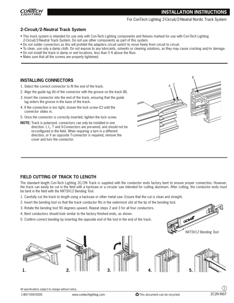
For ConTech Lighting 2-Circuit/2-Neutral Nordic Track System 2-Circuit/2-Neutral Track System • This track system is intended for use only with Con-Tech Lighting components and fixtures marked for use with Con-Tech Lighting 2-Circuit/2-Neutral Track System. Do not use other components as part of this system. • Do not solder connectors as this will prohibit the adapters circuit switch to move freely from circuit to circuit. • To clean, use only a damp cloth. Do not expose to any lubricants, solvents or cleaning solutions, as they may cause cracking and/or damage. • Do not install the track in damp or wet locations, less than 5 ft above the floor. • Make sure that all the screws are properly tightened. B INSTALLING CONNECTORS A C 1. Select the correct connector to fit the end of the track. 2. Align the guide lug (A) of the connector with the groove on the track (B). 3. Insert the connector into the end of the track, ensuring that the guide lug enters the groove in the base of the track. 4. If the connection is too tight, loosen the lock screw (C) until the connector slides in. 5. Once the connector is correctly inserted, tighten the lock screw. NOTE: Track is polarized, connectors can only be installed in one direction. I, L, T and X-Connectors are pre-wired, and should not be re-configured in the field. When requiring a turn in a different direction, or if an opposite T-connector is required, remove the cover and turn the connector. FIELD CUTTING OF TRACK TO LENGTH The standard length Con-Tech Lighting 2C/2N Track is supplied with the conductor ends factory bent to ensure proper connection. However, the track can easily be cut in the field with a hacksaw or a circular saw intended for cutting aluminum. After cutting, the conductor ends must be bent in the field with the NXTSV12 Bending Tool. 1. Carefully cut the track to length using a hacksaw or other metal saw. Ensure that the cut is clean and straight. 2. Insert the bending tool so that the track conductor fits in the outermost slot at the tip of the bending tool. 3. Rotate the bending tool 90 degrees upward. Repeat steps 2 and 3 for all four conductors. 4. Bent conductors should look similar to the factory finished ends, as shown. 5. Confirm correct bending by inserting the opposite end of the tool in the end of the track. NXTSV12 Bending Tool 1. 2. 3. 4. 1 All specifications subject to change without notice. 1-847-559-5500 www.contechlighting.com 5. This document can be recycled. 2C2N INST For ConTech Lighting 2-Circuit/2-Neutral Nordic Track System FIELD DRILLING OF MOUNTING HOLES If track is field cut, it may be necessary to drill new mounting holes. If so, use one of the off-cut pieces as a template for new hole(s) to be drilled. The drill bit should be no larger than 1/4" in diameter. The hole should be centered in the groove in the bottom of the track. Remove burrs after drilling. Hole location should be in accordance with the note below. Hole Location; Max. Dia. 1/4" NOTE: A single section of track that is 4 feet or less in length must have one mounting hole spaced a maximum of 6" from each end of the track section. Additional mounting holes may be needed. A single section of track that is greater than 4 feet in length must have mounting holes spaced a maximum of 12" from each end of the track section, with additional holes at a minimum of every 4 feet along the length of the track section. MOUNTING THE TRACK: SURFACE MOUNT NOTE: Track should be securely mounted at maximum intervals of 4ft, and must be mounted in accordance with all applicable codes and standards. Mark the location of the centerline of the track on the ceiling or support structure. Direct Ceiling Mount Using an appropriate screw or toggle bolt, secure track at the correct position directly to the ceiling through the mounting holes. T-Bar Ceiling Grid Use the NSKBT12 Track Mounting Clips for securing the track to T-bar ceiling grids. Use the NSKBX12 Deep Tile Track Mounting Clips for T-bar grid recessed into the ceiling tile.Snap the clips onto the grid in the correct locations, then insert the track, tightening the set screws while holding the track in position. 2 All specifications subject to change without notice. 1-847-559-5500 www.contechlighting.com This document can be recycled. 2C2N INST For ConTech Lighting 2-Circuit/2-Neutral Nordic Track System MOUNTING THE TRACK: SUSPENDED TRACK Cable Mount Threaded Rod Insert cable through the small center hole of NSKB12 mounting clip so the clip hangs with the flat surface on top. Using NSKB30, or other appropriate hardware, secure cable to ceiling or support structure so the clip is at the desired track mounting height. Loosen the setscrew on the side of the mounting clip and insert the track. Tighten the setscrews while holding track in position. Using NSKB30, or other appropriate hardware, secure threaded rod to ceiling or support structure. Put nut on the threaded rod about a 1/4" from the end. Insert the threaded rod through the slotted hole in the clip, add second nut below the clip. Tighten both nuts so end of threaded rod is flush with bottom nut. Loosen set screw on side of mounting clip and insert track. Tighten the set screw while holding track in position. Stem Mount Secure mounting bracket to outlet box using hardware provided or other appropriate fasteners. Thread one nut on upper end of feed stem. Attach upper threaded portion of stem to mounting bracket and secure second nut tightly. Loosen lock screw and slide canopy up stem, taking care not to scratch the surface finish. Tighten canopy once in position. Remove plastic cover from SP4P mounting bracket. Using a sharp knife, cut out the top protrusion to allow the feed stem to pass through cover. Slide cover up stem. Thread SP4P metal bracket onto stem and tighten. Secure mounting bracket to back of track, fastening the set screws. Slide mounting bracket cover down the stem and over the mounting bracket. 3 All specifications subject to change without notice. 1-847-559-5500 www.contechlighting.com This document can be recycled. 2C2N INST For ConTech Lighting 2-Circuit/2-Neutral Nordic Track System ELECTRICAL CONNECTION 120V~Max. 20A/cct Ground Line2 L2 Line1 L1 Neutral2 N2 Max. 20A Neutral1 N1 Max. 20A L1 L2 N1 N2 The Con-Tech Lighting 2-Circuit/2-Neutral Track System is designed to be fed by two branch circuits rated 120VAC, 20A; eg. the system is a two-circuit/two-neutral track and care must be taken to keep designated circuits 1and 2 separate. INSTALLATION OF TRACK TO AN OUTLET BOX 1. Remove the knock-out hole provided on the back side of the feed connector. Remove feed connector cover. 2. Pass the supply, neutral and ground wires through the canopy cover. 3. Attach feed connector to track (NOTE: track is polarized and feed connector will only fit one end of track). Pass wires through hole on feed and mount track to ceiling using toggle bolts or screws. 4. ALWAYS CONNECT GROUND WIRE TO GREEN GROUND TERMINAL. Connect live conductors to the appropriate terminal marked “L1”, or “L2”. Connect neutral conductors to the appropriate terminal marked “N1” or “N2”. 5. Replace feed connector cover plate. ELECTRICAL FEED THROUGH PENDANT FEED STEM 1. Secure mounting bracket to outlet box using hardware provided. 2. Thread one nut on upper end of feed stem. Pass required supply wires and ground wire through second nut and through feed stem. OUTLET BOX 3. Attach upper threaded portion of stem to mounting bracket and secure second nut tightly. Loosen lock screw and slide canopy up stem, taking care not to scratch the surface finish. Tighten canopy once in position. 4. Remove plastic cover from SP4E mounting bracket. Use a sharp knife to cut out the top protrusion to allow the feed stem to pass through cover. Slide cover up stem while completing remaining connections. Pass supply and ground wires through metal bushing of SP4E mounting bracket. Thread bracket onto stem and tighten. 5. Cut out knock-out on back side of live end feed connector using a sharp knife. Pass wires from the mounting bracket through the knock-out and attach live end to track. Secure mounting bracket to back of track, fastening the set screws. 6. Attach supply leads and ground wire to proper screw terminals in the live end and replace the cover. Slide mounting bracket cover down the stem and over the mounting bracket. 4 All specifications subject to change without notice. 1-847-559-5500 www.contechlighting.com This document can be recycled. 2C2N INST For ConTech Lighting 2-Circuit/2-Neutral Nordic Track System FEEDING TRACK AT A CONNECTOR Con-Tech Lighting 2-Circuit/2-Neutral Track System can be fed at the following corners and track intercept connectors. When feeding at one of the connectors, follow the feeding instructions as shown under ‘INSTALLATION OF TRACK TO AN OUTLET BOX’. NOTE: The track is polarized, so connectors can only be installed in the track in one direction. I, L, T, X-connectors are pre-wired, and should not be re-configured in the field. When requiring a turn in a different direction, or if an opposite T-connector is required,remove the cover and turn the connector as shown above. Live Middle Feed NTEK14 - 120V NHTEK14 - 277V Feedable T-Connector Adj. Right Polarity NTEK39 - 120V NHTEK39 - 277V Feedable T-Connector Adj. Left Polarity NTEK40 - 120V NHTEK40 - 277V Feedable L-Connector Adj. Polarity NTEK34 - 120V NHTEK34 - 277V Feedable X-Connector Adj. Left Polarity NTEK38 - 120V NHTEK38 - 277V INSTALLING AND REMOVING FIXTURES To reduce the risk of fire and electric shock, use only fixtures marked for use with Con-Tech Lighting 2-Circuit/2-Neutral Track System. Fixtures with an adapter are factory wired and can not be field modified. Fixtures must be returned to the manufacturer for modification of the circuit selection. DO NOT slide the adapter down the track as it will damage the connectors and cause faulty lighting. Fixture must be taken out of track and placed to its desired location. 120V System 1. Align the fixture adapter so that the flange (ridge) on the track is on the same side as the locking knob on the adapter. 2. Insert the adapter into the track (A), turning it at the same time to the right (B) until the locking knob snaps into place behind the flange. NOTE: Ensure that the adapter is turned enough so that the knob positively snaps into place over the flange. A 3. To remove the adapter, push the locking knob and pull the fixture assembly out, turning it to the left at the same time. B 277V System 1. Align the ridge on the fixture adapter with the groove on the track. 2. Push the adapter into the track till it snaps into place. 3. Turn the mechanical fixing knob clockwise. Mechanical Fixing Knob 4. Select the desired circuit with the circuit selector knob. Locks Fixture in Track 5. To remove the adapter from track, select the “0”position (OFF) before turning the mechanical fixing knob counterclockwise. Pull from fixing knob end. Circuit Selector 1-847-559-5500 www.contechlighting.com 0 (Off) 5 All specifications subject to change without notice. This document can be recycled. 2C2N INST For ConTech Lighting 2-Circuit/2-Neutral Nordic Track System IMPORTANT SAFETY INSTRUCTIONS: • Read all the instructions before installation. Save instructions for later use. • Turn off the power at fuse or circuit breaker box before installation or maintenance work. • Wear rubber soled shoes and work on a sturdy wooden or non-conductive ladder. • Product must be mounted in locations and at heights in compliance with National Electrical Code and local building codes. For indoor, dry location use only. • Do not exceed the nominal supply voltage or amperage ratings. • Installing contrary to instructions may cause unsafe conditions. • Warning: Risk of fire. Most dwellings built before 1985 have supply wire rated at 60°C. Consult a qualified electrician before installation. • Avoid hazards to children: account for all parts and properly dispose of all packing materials. • Call the Technical Support department at ConTech Lighting with any installation questions. 6 All specifications subject to change without notice. 1-847-559-5500 www.contechlighting.com This document can be recycled. 2C2N INST
