AIRWAVe VIsuALRF ™ data sheet
advertisement
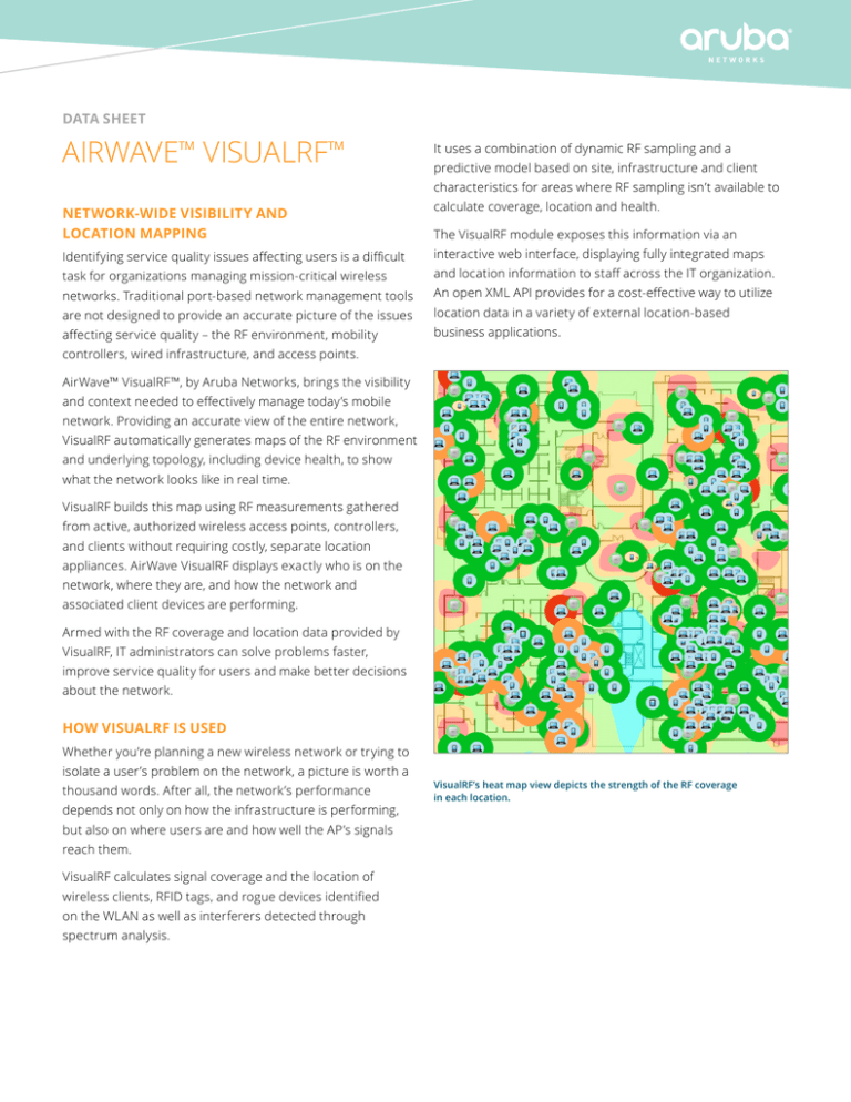
data sheet Airwave™ visualrf™ It uses a combination of dynamic RF sampling and a predictive model based on site, infrastructure and client characteristics for areas where RF sampling isn’t available to Network-wide Visibility and Location Mapping calculate coverage, location and health. Identifying service quality issues affecting users is a difficult interactive web interface, displaying fully integrated maps task for organizations managing mission-critical wireless and location information to staff across the IT organization. networks. Traditional port-based network management tools An open XML API provides for a cost-effective way to utilize are not designed to provide an accurate picture of the issues location data in a variety of external location-based affecting service quality – the RF environment, mobility business applications. The VisualRF module exposes this information via an controllers, wired infrastructure, and access points. AirWave™ VisualRF™, by Aruba Networks, brings the visibility and context needed to effectively manage today’s mobile network. Providing an accurate view of the entire network, VisualRF automatically generates maps of the RF environment and underlying topology, including device health, to show what the network looks like in real time. VisualRF builds this map using RF measurements gathered from active, authorized wireless access points, controllers, and clients without requiring costly, separate location appliances. AirWave VisualRF displays exactly who is on the network, where they are, and how the network and associated client devices are performing. Armed with the RF coverage and location data provided by VisualRF, IT administrators can solve problems faster, improve service quality for users and make better decisions about the network. HOW VISUALRF IS USED Whether you’re planning a new wireless network or trying to isolate a user’s problem on the network, a picture is worth a thousand words. After all, the network’s performance depends not only on how the infrastructure is performing, but also on where users are and how well the AP’s signals reach them. VisualRF calculates signal coverage and the location of wireless clients, RFID tags, and rogue devices identified on the WLAN as well as interferers detected through spectrum analysis. VisualRF’s heat map view depicts the strength of the RF coverage in each location. data sheet Airwave™ VISUALRF™ Key Features Simple setup process • No need for additional dedicated sensors, exciters or location servers • Imports existing building floor plans and maps from thirdparty tools • Supports DWG, DWF and DFX CAD, PDFfile formats as well as common image file formats • Batch upload tool can import hundreds of floor plans at one time • Automatically discovers and polls devices via AirWave • Automatically tracks any device that associates with the network, including laptop computers, PDAs, wireless VoIP phones, scanner guns and many Wi-Fi asset tags • Automatically tracks non-802.11 devices that interfere with your wireless network Effective site planning — deploy your network right the first time • Determines the right quantity and placement of APs, controllers and switches based on your coverage goals • Supports 3rd party AP and network infrastructure products • Incorporates switches and wiring closets into network design • Automatically generates bill of material reports in • Integrates with Aruba Mobility Controlers to gather and display health statistics on client devices that indicate which clients are experiencing connectivity problems and where they are located Open architecture • XML API enables cost-effective integration of valuable location data with other applications Accurate location data • Determines GPS location coordinates for APs and controllers on any floor plan by setting latitude and longitude coordinates, and displays altitude as floor number • Allows quick location of users and wireless devices for troubleshooting, planning and asset tracking • Generally achieves resolution below 10 meters — horizontally and vertically — without requiring special sensors or site surveys • Plays back a user’s location history over the past day to aid in troubleshooting and recovery of lost devices as well as UCC call quality • Last known location of each tracked device helps organizations find lost or stolen devices RF statistics Microsoft Word formats to simplify the quote and RF Statistics allow AirWave administrators to track and physical deployment process display various RF information over a specified period of time ® VisualRF plan: Free standalone planning tool for detailed analysis of: • Runs on Windows-based laptops and workstations • RF channels, power, and noise • Uses the same RF planning and visualization algorithms • ARM events as VisualRF • Allows plans made offline to be imported into VisualRF (and vice versa) Efficient troubleshooting • Different visual overlays display heat maps of expected • Active sources of interference • Other relevant data used to generate specific RF health reports VisualRF overlays • Overlays provide powerful visual tools for quickly signal quality, expected 802.11 data rates, channel diagnosing and troubleshooting issues that can impact utilization, upstream relationships between APs and wiring the service quality of an Aruba Mobility-Defined network. closets and the number of radios that can serve a voice client at every point on a floor plan • Automatically recalculates coverage maps and device locations as it receives real-time data from the wireless LAN infrastructure • Performs what-if analysis for proactive coverage planning by simulating the failure of a number of deployed radios AirWave VisualRF overlays include: • AppRF: visualize application usage and performance by client for the top ten most popular applications • UCC: visibility into device, user and call quality to identify calls with good, fair and poor quality • Client Health: distinguish between healthy and poor performing clients across a coverage area or floor plan • Voice: displays network health and coverage for voice communications over Wi-Fi data sheet Airwave™ VISUALRF™ • Channel: displays overlapping regions for all channels or individual channels of the Wi-Fi network • Channel Utilization: displays the airtime utilization for transmit, receive, interference or all data sets • Heatmap: displays coverage based on signal strength of the Wi-Fi network • Speed: displays coverage based on the transmit power of Wi-Fi clients Better security • View locations of rogue APs discovered by AirWave RAPIDS™ for faster investigation and threat removal • Plan the proper locations for dedicated Wi-Fi sensors such as Aruba Air Monitors to ensure complete coverage of your organization’s RF environment 1344 Crossman Ave | Sunnyvale, CA 94089 1.866.55.ARUBA | T: 1.408.227.4500 | FAX: 1.408.227.4550 | info@arubanetworks.com www.arubanetworks.com DS_AirWaveVisualRF_072814
