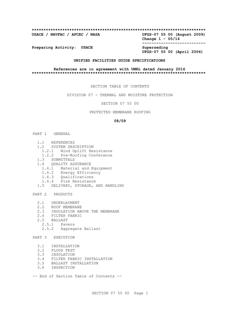
************************************************************************** USACE / NAVFAC / AFCEC / NASA ...
advertisement

************************************************************************** USACE / NAVFAC / AFCEC / NASA UFGS-07 55 00 (August 2009) Change 1 - 05/14 --------------------------Preparing Activity: USACE Superseding UFGS-07 55 00 (April 2006) UNIFIED FACILITIES GUIDE SPECIFICATIONS References are in agreement with UMRL dated January 2016 ************************************************************************** SECTION TABLE OF CONTENTS DIVISION 07 - THERMAL AND MOISTURE PROTECTION SECTION 07 55 00 PROTECTED MEMBRANE ROOFING 08/09 PART 1 GENERAL 1.1 REFERENCES 1.2 SYSTEM DESCRIPTION 1.2.1 Wind Uplift Resistance 1.2.2 Pre-Roofing Conference 1.3 SUBMITTALS 1.4 QUALITY ASSURANCE 1.4.1 Material and Equipment 1.4.2 Energy Efficiency 1.4.3 Qualifications 1.4.4 Fire Resistance 1.5 DELIVERY, STORAGE, AND HANDLING PART 2 PRODUCTS 2.1 UNDERLAYMENT 2.2 ROOF MEMBRANE 2.3 INSULATION ABOVE THE MEMBRANE 2.4 FILTER FABRIC 2.5 BALLAST 2.5.1 Pavers 2.5.2 Aggregate Ballast PART 3 3.1 3.2 3.3 3.4 3.5 3.6 EXECUTION INSTALLATION FLOOD TEST INSULATION FILTER FABRIC INSTALLATION BALLAST INSTALLATION INSPECTION -- End of Section Table of Contents -- SECTION 07 55 00 Page 1 ************************************************************************** USACE / NAVFAC / AFCEC / NASA UFGS-07 55 00 (August 2009) Change 1 - 05/14 --------------------------Preparing Activity: USACE Superseding UFGS-07 55 00 (April 2006) UNIFIED FACILITIES GUIDE SPECIFICATIONS References are in agreement with UMRL dated January 2016 ************************************************************************** SECTION 07 55 00 PROTECTED MEMBRANE ROOFING 08/09 ************************************************************************** NOTE: This guide specification covers the requirements for protected membrane roof system. Adhere to UFC 1-300-02 Unified Facilities Guide Specifications (UFGS) Format Standard when editing this guide specification or preparing new project specification sections. Edit this guide specification for project specific requirements by adding, deleting, or revising text. For bracketed items, choose applicable items(s) or insert appropriate information. Remove information and requirements not required in respective project, whether or not brackets are present. Comments, suggestions and recommended changes for this guide specification are welcome and should be submitted as a Criteria Change Request (CCR). ************************************************************************** PART 1 GENERAL ************************************************************************** NOTE: This specification covers a roofing system in which the membrane is protected by an overlay of extruded polystyrene insulation, a filter fabric, and a layer of ballast on top. The surface of overhangs must be sealed to prevent leakage of air and, therefore, uplift. For additional guidance on PMR, the designer should consult the National Roofing Contractors Association (NRCA) Roofing and Waterproofing Manual. Roof must be constructed with a minimum slope of 1 to 48, and a maximum slope of 1 to 6. Drainage is critical as the insulation will float if submerged and not adequately ballasted. Where internal drains are not used, ice dams may occur at eaves and SECTION 07 55 00 Page 2 scuppers. For guidance on flashings and drainage details, the designers should consult the SMACNA "Architectural Sheet Metal Manual." Undersides of the deck, including overhangs, should be sealed when using loose-laid protected membrane to prevent wind from pressurizing the underside of the membrane. Bituminous membranes should be flood-coated and not surfaced with aggregate. Polystyrene should not be placed in contact with asphalt. Except where exposed drain baskets pose a safety hazard, there must be an opening in the insulation, filter fabric, and ballast above each drain basket. Pavers above hidden drains will be marked so that the drains can be inspected periodically. Designer should require materials, products, and innovative construction methods and techniques which are environmentally sensitive, take advantage of recycling and conserve natural resources. ************************************************************************** 1.1 REFERENCES ************************************************************************** NOTE: This paragraph is used to list the publications cited in the text of the guide specification. The publications are referred to in the text by basic designation only and listed in this paragraph by organization, designation, date, and title. Use the Reference Wizard's Check Reference feature when you add a RID outside of the Section's Reference Article to automatically place the reference in the Reference Article. Also use the Reference Wizard's Check Reference feature to update the issue dates. References not used in the text will automatically be deleted from this section of the project specification when you choose to reconcile references in the publish print process. ************************************************************************** The publications listed below form a part of this specification to the extent referenced. The publications are referred to within the text by the basic designation only. ASTM INTERNATIONAL (ASTM) ASTM C1177/C1177M (2013) Standard Specification for Glass Mat Gypsum Substrate for Use as Sheathing ASTM C1396/C1396M (2014a) Standard Specification for Gypsum Board SECTION 07 55 00 Page 3 ASTM C29/C29M (2009) Standard Test Method for Bulk Density ("Unit Weight") and Voids in Aggregate ASTM C578 (2015b) Standard Specification for Rigid, Cellular Polystyrene Thermal Insulation ASTM C726 (2012) Mineral Fiber Roof Insulation Board ASTM D448 (2012) Sizes of Aggregate for Road and Bridge Construction ASTM D4751 (2012) Determining Apparent Opening Size of a Geotextile ASTM D5034 (2009; R 2013) Breaking Strength and Elongation of Textile Fabrics (Grab Test) ASTM D751 (2006; R 2011) Coated Fabrics FM GLOBAL (FM) FM APP GUIDE (updated on-line) Approval Guide http://www.approvalguide.com/ FM P9513 (2002) Specialist Data Book Set for Roofing Contractors; contains 1-22 (2001), 1-28 (2002), 1-29 (2002), 1-28R/1-29R (1998), 1-30 (2000), 1-31 (2000), 1-32 (2000), 1-33 (2000), 1-34 (2001), 1-49 (2000), 1-52 (2000), 1-54 (2001) SINGLE PLY ROOFING INDUSTRY (SPRI) SPRI RP-4 (2008) Wind Design Standard for Ballasted Single-Ply Roofing Systems U.S. ENVIRONMENTAL PROTECTION AGENCY (EPA) Energy Star (1992; R 2006) Energy Star Energy Efficiency Labeling System (FEMP) U.S. NATIONAL ARCHIVES AND RECORDS ADMINISTRATION (NARA) PL 109-58 Energy Policy Act of 2005 (EPAct05) UNDERWRITERS LABORATORIES (UL) UL 580 (2006; Reprint Oct 2013) Tests for Uplift Resistance of Roof Assemblies UL 790 (2004; Reprint Jul 2014) Standard Test Methods for Fire Tests of Roof Coverings SECTION 07 55 00 Page 4 1.2 1.2.1 SYSTEM DESCRIPTION Wind Uplift Resistance ************************************************************************** NOTE: Design should be in accordance with SPRI RP-4. Fully adhered protected membranes have performed well in hurricane areas when ballasted as specified in SPRI RP-4. Roof deck must be adequate to support weight of ballast as dead load. ************************************************************************** Wind uplift resistance of the complete roof assembly shall be rated Class I-[60] [90] in accordance with UL 580. Wind resistance of loose-laid ballasted system shall be in accordance with [FM P9513] [SPRI RP-4]. Submit drawings required for the membrane, modified to include the complete PMR assembly. 1.2.2 Pre-Roofing Conference After approval of submittals and before performing roofing [and insulation] installation work, hold a pre-roofing conference to review the following: a. Drawings, specifications and submittals related to the roof work b. Roof system components installation c. Procedure for the roof manufacturer's technical representative's onsite inspection and acceptance of the roofing substrate, the name of the manufacturer's technical representatives, the frequency of the onsite visits, distribution of copies of the inspection reports from the manufacturer's technical representatives to roof manufacturer d. Plan for coordination of the work of the various trades involved in providing the roofing system and other components secured to the roofing e. Quality control plan for the roof system installation f. Safety requirements Coordinate pre-roofing conference scheduling with the Contracting Officer. The conference shall be attended by the Contractor, the Contracting Officer's designated personnel, and personnel directly responsible for the installation of roofing [and insulation], flashing and sheet metal work, [[mechanical][and][electrical] work], other trades interfacing with roof work , [Fire Marshall,] and representative of the roofing materials manufacturer. Before beginning roofing work, provide a copy of meeting notes and action items to all attending parties. Note action items requiring resolution prior to start of roof work. 1.3 SUBMITTALS ************************************************************************** NOTE: Review submittal description (SD) definitions in Section 01 33 00 SUBMITTAL PROCEDURES and edit the following list to reflect only the submittals required for the project. The Guide Specification technical editors have SECTION 07 55 00 Page 5 designated those items that require Government approval, due to their complexity or criticality, with a "G." Generally, other submittal items can be reviewed by the Contractor's Quality Control System. Only add a “G” to an item, if the submittal is sufficiently important or complex in context of the project. For submittals requiring Government approval on Army projects, a code of up to three characters within the submittal tags may be used following the "G" designation to indicate the approving authority. Codes for Army projects using the Resident Management System (RMS) are: "AE" for Architect-Engineer; "DO" for District Office (Engineering Division or other organization in the District Office); "AO" for Area Office; "RO" for Resident Office; and "PO" for Project Office. Codes following the "G" typically are not used for Navy, Air Force, and NASA projects. An "S" following a submittal item indicates that the submittal is required for the Sustainability Notebook to fulfill federally mandated sustainable requirements in accordance with Section 01 33 29 SUSTAINABILITY REPORTING. Choose the first bracketed item for Navy, Air Force and NASA projects, or choose the second bracketed item for Army projects. ************************************************************************** Government approval is required for submittals with a "G" designation; submittals not having a "G" designation are for [Contractor Quality Control approval.] [information only. When used, a designation following the "G" designation identifies the office that will review the submittal for the Government.] Submittals with an "S" are for inclusion in the Sustainability Notebook, in conformance to Section 01 33 29 SUSTAINABILITY REPORTING. Submit the following in accordance with Section 01 33 00 SUBMITTAL PROCEDURES: SD-02 Shop Drawings Roof Assembly SD-07 Certificates Material and Equipment Energy Efficiency Qualifications 1.4 1.4.1 QUALITY ASSURANCE Material and Equipment Submit material supplier's or equipment manufacturer's statement that the supplied insulation, filter fabric and membrane materials meet specified requirements. Each certificate shall be signed by an official authorized to certify on behalf of material supplier or product manufacturer and shall SECTION 07 55 00 Page 6 identify quantity and date or dates of shipment or delivery to which the certificates apply. Submit certificates of compliance for material and equipment, as specified. 1.4.2 Energy Efficiency Provide products that meet or exceed the specified energy efficiency requirements of FEMP designated or Energy Star qualified products. Submit documentation certifying that product conforms to PL 109-58 by meeting or exceeding Energy Star or FEMP efficiency requirements as defined at "Energy-Efficient Products" at http://www1.eere.energy.gov/femp/procurement. Indicate Energy Efficiency Rating. 1.4.3 Qualifications Submit documentation verifying a minimum of 2 years experience with PMR systems and certification by the PMR manufacturer as an approved Installer for the specified PMR system. 1.4.4 Fire Resistance The completed roof system shall be rated Class A as determined by UL 790 or Class I as determined by FM APP GUIDE. Compliance of each component of the roofing system shall be evidenced by the label or written certification from the manufacturer. 1.5 DELIVERY, STORAGE, AND HANDLING Store insulation away from areas where welding is being performed or where contact with open flames is possible. Shield insulation from extended exposure to sunlight. Remove materials damaged by moisture from the site. Ballast shall not be stored on the roof. PART 2 PRODUCTS ************************************************************************** NOTE: Insulation to be placed beneath the membrane is described in Section 07 22 00 ROOF AND DECK INSULATION. ************************************************************************** 2.1 UNDERLAYMENT ************************************************************************** NOTE: Loose-laid membrane will not be placed directly on concrete or other hard, potentially rough deck. ************************************************************************** Underlayment may be [concrete] [any insulation which is suitable for the particular membrane] [mineral fiberboard in accordance with ASTM C726][ or ][gypsum board in accordance with ASTM C1396/C1396M, 16 mm 5/8 inch thick or glass mat gypsum roof board in accordance with ASTM C1177/C1177M, [6.35 mm 1/4 inch] [12.7 mm 1/2 inch] [15.87 mm 5/8 inch]]. 2.2 ROOF MEMBRANE ************************************************************************** NOTE: Specify built-up roof, EPDM, modified bitumen SECTION 07 55 00 Page 7 roofing, or PVC roof membrane, or allow Contractor to choose from these options. Delete each inapplicable roof membrane. When editing these paragraphs, delete aggregate surfacing, walkways, and types of insulation not used. Specify Section 07 51 13 ASPHALT BUILT-UP ROOFING when membrane is applied directly to concrete deck, and require two final bitumen flood coats, each coat providing 1.5 kg of bitumen per square meter 30 pounds per square. ************************************************************************** Roof membrane shall be in accordance with Section [07 51 13 ASPHALT BUILT-UP ROOFING] [07 53 23 ETHYLENE-PROPYLENE-DIENE-MONOMER ROOFING] [ 07 54 19 POLYVINYL CHLORIDE ROOFING] [ or ] [07 52 00 MODIFIED BITUMINOUS MEMBRANE ROOFING]. 2.3 INSULATION ABOVE THE MEMBRANE ************************************************************************** NOTE: Determine the required R-value and show the R-value at the appropriate detail on the drawings. The required R-value will never be less than that used in the Energy Budget Analysis. Specify a vapor retarder only when required by calculations made as specified in ASTM Manual 18 "Moisture Control in Buildings" or in the CRREL-EC report "Vapor Retarders for Membrane Roofing Systems." ************************************************************************** Insulation placed above the membrane shall be extruded polystyrene, or extruded polystyrene with a mortar face. Insulation shall be a standard product of the manufacturer, and shall be factory marked with the manufacturer's name or trade mark, the material specification number, the R-value at 24 degrees C 75 degrees F, and the thickness. Boards shall be marked individually. The thermal resistance of the insulation shall be not less than the R-value shown on the drawings. Insulation shall conform to ASTM C578, Type V, VI or VII and shall be intended by the manufacturer for use above a protected roof membrane. Bottom layer of insulation shall provide drainage paths, mostly parallel to the slope, between insulation and membrane. Top surface of mortar-faced insulation shall be 10 mm 3/8 inch thick portland cement latex mortar having minimum properties as follows: specific gravity: 2.0, compressive strength: 20.7 MPa 3000 psi and bond strength to insulation: 69 kPa 10 psi. Top layer of insulation may have ribbed top surfaces when flat-bottom pavers are used as ballast. Comply with EPA requirements in accordance with Section 01 33 29 SUSTAINABILITY REPORTING. 2.4 FILTER FABRIC Filter fabric shall be either woven or non-woven pervious sheet of long chain polymeric filaments or yarns such as polypropylene, polyethylene, polyester, polyamide, or polyvinylidene-chloride, formed into a pattern with distinct and measurable openings. The filter fabric shall provide an ASTM D4751 Apparent Opening Size (AOS) no finer than the 0.125 mm No. 120 sieve and no coarser than the 0.212 mm No. 70 sieve. Edges of fabric shall be selvaged or otherwise finished to prevent raveling. Fabric shall have minimum weight of 102 gms/sq. m 3 oz/sq. yard and shall conform to the SECTION 07 55 00 Page 8 following table: Property Test Procedure Result Tensile strength ASTM D5034 Grab test method using 25 mm 1 inch square jaws and a travel rate of 55 mm per sec 12 inches per minute 29 kg/25 mm65 lbs/inch minimum in any principal direciton Puncture strength ASTM D751 - Tension testing machine with ring clamp; steel ball replaced with a 8 mm 5/16 inch diameter solid steel cylinder with a hemispherical tip centered within the ring clamp 18 kg40 lbs minimum load 2.5 BALLAST ************************************************************************** NOTE: Pavers are preferred over aggregate ballast, and a combination of pavers and ballast is preferred over aggregate only. Determine ballast and/or paver size and quantity using SPRI RP-4 and modify paragraph BALLAST INSTALLATION accordingly. SPRI RP-4 allows crushed stone over protected membrane. Use light-colored aggregate when locally available. Small aggregate will not be used in vicinity of aircraft operations; however, rock or paver ballast may be used in such areas. Where ambient temperatures drop below freezing, avoid use of ballast or pavers that will break during freeze-thaw cycles. Installations where this roofing system is used should be monitored; any problems or noteworthy benefits encountered in the use of this system should be brought to the attention of HQUSACE (CEMP-ET) WASH DC 20314-1000 for information and possible dissemination. ************************************************************************** Ballast shall be screened gravel, screened crushed stone, precast concrete pavers, or extruded polystyrene insulation with integral mortar topping. Size and placement shall be as indicated. Selected ballast exposed to sunlight must have an initial solar reflectance greater or equal to 0.65 and a solar reflectance greater or equal to 0.50 three years after installation under normal conditions. 2.5.1 Pavers Concrete pavers shall be air-entrained concrete, minimum 38 mm 1-1/2 inches thick, having 21 MPa 3000 psi minimum compressive strength. Pavers shall be ribbed on the bottom for use over smooth topped insulation and flat on the bottom for use over insulation with ribbed top. SECTION 07 55 00 Page 9 2.5.2 Aggregate Ballast Gravel and crushed stone shall conform to ASTM D448, Size 4 and 2, with less than 2 percent that passes through a 10 mm 3/8 inch screen. Ballast shall have minimum unit mass of 960 kg/cubic meter 60 pcf as determined by ASTM C29/C29M. PART 3 3.1 EXECUTION INSTALLATION Install roof membrane and flashing in accordance with Sections [07 51 13 ASPHALT BUILT-UP ROOFING] [07 53 23 ETHYLENE-PROPYLENE-DIENE-MONOMER ROOFING] [07 54 19 POLYVINYL CHLORIDE ROOFING] [or] [07 52 00 MODIFIED BITUMINOUS MEMBRANE ROOFING]. 3.2 FLOOD TEST After the membrane and its flashings are installed, and before the insulation is placed above the membrane, plug the drains and flood the roof with water for 24 hours. Leaks shall be remedied before insulation is installed. 3.3 INSULATION ************************************************************************** NOTE: Specify or indicate a 0.13 mm 4 mil polyethylene sheet below the insulation when surface is flood coat bitumen. ************************************************************************** Insulation shall be loose laid on the membrane after the membrane is completed and flood coat (if any) is cool. When required by the manufacturer of the insulation, a slip sheet shall be installed over the membrane. Drainage paths shall be provided between the lower surface of the insulation and the membrane. Most of the drainage paths shall be parallel to the slope of the roof. Unless otherwise specified by the manufacturer, end joints shall be staggered. Joints between boards shall not exceed 6 mm 1/4 inch. Insulation shall be installed to within 19 mm 3/4 inch of projections and cant strips. 3.4 FILTER FABRIC INSTALLATION Filter fabric shall be laid loose over insulation, smooth and free of tension and stress. Edges and ends shall be lapped a minimum of 300 mm 1 foot and extended above the ballast 50 to 75 mm 2 to 3 inches at the perimeter and penetrations. Joints parallel to perimeter will not be permitted within 1.8 meters 6 feet of the perimeter. 3.5 BALLAST INSTALLATION Place ballast to provide a weight of 479 Pa 10 psf on the roof area, except that the weight shall be 957 Pa 20 psf within 1.2 meters 4 feet of the roof perimeter. At approved intervals, the placed ballast shall be weighed and corrected to be within plus or minus 10 percent of specified weight. Pavers shall be installed where indicated. Pavers above hidden drains shall be marked so that drains may be inspected. Interior roof drains shall be surrounded with gravel or stone graded between 25 and 38 mm 1 and SECTION 07 55 00 Page 10 1-1/2 inches to the level of ballast over insulation or to mid-height of drain bonnet, whichever is lower. During placement of aggregate ballast, drains and other openings shall be covered to prevent inadvertent entry of ballast. Ballast buggy wheels are not allowed on the membrane. 3.6 INSPECTION ************************************************************************** NOTE: Where justified by the amount or criticality of the insulation and roofing involved, and similar requirements are not established for the Contractor Quality Control Organization specified elsewhere, the following INSULATION TECHNICIAN and inspection requirements may be added: "INSULATION TECHNICIAN A roof insulation technician responsible directly to the Contractor and experienced in the installation of roof insulation and related work shall perform the inspection functions and shall be on the site whenever roof insulation operations are in progress." ************************************************************************** Establish and maintain an inspection procedure to ensure compliance of the installed roof with the contract requirements. Any work found not to be in compliance with the contract shall be promptly removed and replaced or corrected in an approved manner. Inspection shall include, but not be limited to, the following: a. Observation of environmental conditions; number and skill level of roofing workers; start and end time of various tasks; condition of substrate. b. Verification of compliance of materials before, during, and after installation, proper storage and handling of insulation. c. Inspection of mechanical fasteners; type, number, length, and spacing. d. Coordination with other materials, cants, nailers, flashings, and penetrations. e. Inspection of proper placement of insulation, joint orientation and laps between layers, joint widths and bearing of edges of underlayment on deck. f. Inspection of proper placement of pavers and amount and leveling of ballast. Submit procedures for approval, prior to start of roofing work including a checklist of points to be observed. The actual inspections shall be documented and a copy of the documentation furnished to the Contracting Officer at the end of each day. -- End of Section -- SECTION 07 55 00 Page 11


