Friction Stir Welding of Hydrided Titanium Alloys Mark Taylor, D.P. Field
advertisement
Friction Stir Welding of Hydrided Titanium Alloys
Mark Taylor, D.P. Field
Multi-Scale Engineering/ Materials Department
During Friction Stir Welding (FSW), a non-consumable
tool spins down an abutted joint, “stirring” material
from both plates into each other. Being a solid-state
welding process, much frictional heating and force is
required of the tool. This steep demand on the tool
give rise to failure after relatively few welds, making it
an uneconomical process. However, by hydriding the
plates, the amount of heat required to begin welding
significantly decreases, which in turn puts a lesser
demand on the tool. However, achieving the desired
beta (β) phase with a lesser force remains to be proven.
With certain relationships between crystallographic
orientations, the resulting microstructure reveals
whether the specimen was welded in a Body Center
Cubic (BCC) β-phase, or if it stayed in a Hexagonal Close
Packed (HCP) α-phase.
From the phase
diagram, it is evident
that when inducing
hydrogen into a
Titanium specimen,
the temperature at
which the allotrophic
phase transformation
from αTi to βTi
decreases.
The Titanium alloy (Ti-6Al-4V) was cross-sectioned, and
ultimately polished to a 0.02µ colloidal silica vibropolish
for fifteen hours. The Field Emission Scanning Electron
Microscope (FESEM) equipped with Electron
Backscatter Diffraction (EBSD) capability was used. The
accompanying software, Orientation Imaging
Microscopy (OIM) Analysis, was used to analyze the
diffraction patterns and to represent the data in various
forms. From the data gathered, only the highconfidence data (≥90% certain) were used. From the
filtered data, pole figures and grain orientation maps
were produced.
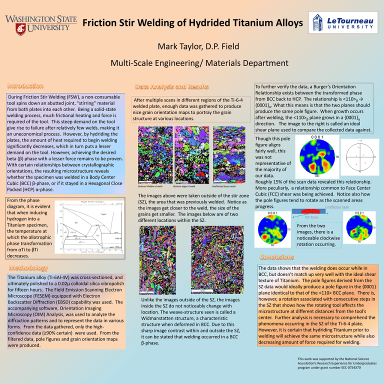
After multiple scans in different regions of the Ti-6-4
welded plate, enough data was gathered to produce
nice grain orientation maps to portray the grain
structure at various locations.
Bottom Middle of weld.
Bottom edge of weld
Unaffected base metal
The images above were taken outside of the stir zone
(SZ), the area that was previously welded. Notice as
the images get closer to the weld, the size of the
grains get smaller. The images below are of two
different locations within the SZ.
To further verify the data, a Burger’s Orientation
Relationship exists between the transformed phase
from BCC back to HCP. The relationship is <110>β →
{0001}α. What this means is that the two planes should
produce the same pole figure. When growth occurs
after welding, the <110>β plane grows in a {0001}α
direction. The image to the right is called an ideal
shear plane used to compare the collected data against.
Though this pole
figure aligns
fairly well, this
was not
representative of
the majority of
our data.
Roughly 15% of the scan data revealed this relationship.
More peculiarly, a relationship common to Face Center
Cubic (FCC) shear was being achieved. Notice also how
the pole figures tend to rotate as the scanned areas
progress.
. .
From the two
images, there is a
noticeable clockwise
rotation occurring.
Unlike the images outside of the SZ, the images
inside the SZ do not noticeably change with
location. The weave-structure seen is called a
Widmanstatten structure, a characteristic
structure when deformed in BCC. Due to this
sharp image contrast within and outside the SZ,
it can be stated that welding occurred in a BCC
β-phase.
The data shows that the welding does occur while in
BCC, but doesn’t match up very well with the ideal shear
texture of Titanium. The pole figures derived from the
SZ data would ideally produce a pole figure in the {0001}
plane identical to that of the <110> BCC plane. There is,
however, a rotation associated with consecutive steps in
the SZ that shows how the rotating tool affects the
microstructure at different distances from the tool’s
center. Further analysis is necessary to comprehend the
phenomena occurring in the SZ of the Ti-6-4 plate.
However, it is certain that hydriding Titanium prior to
welding will achieve the same microstructure while also
decreasing amount of force required for welding.
This work was supported by the National Science
Foundation’s Research Experience for Undergraduates
program under grant number EEC-0754370


