Solution of ECE 315 Test 12 F04
advertisement
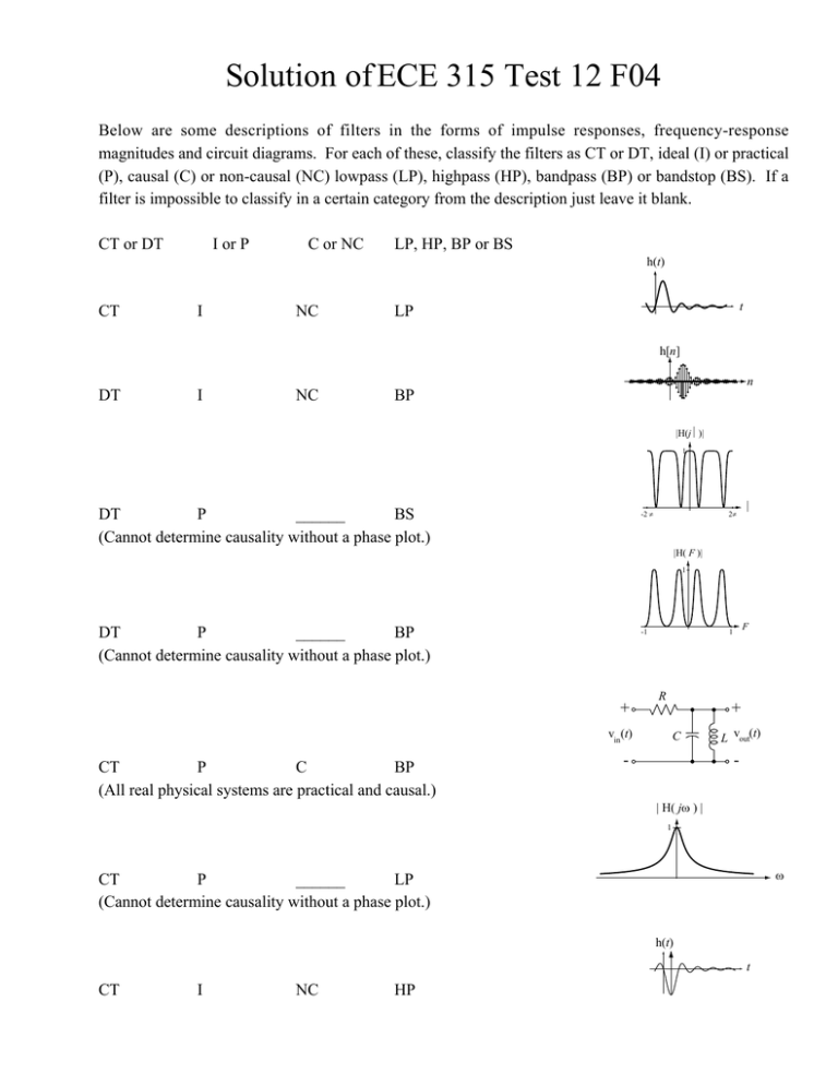
Solution of ECE 315 Test 12 F04 Below are some descriptions of filters in the forms of impulse responses, frequency-response magnitudes and circuit diagrams. For each of these, classify the filters as CT or DT, ideal (I) or practical (P), causal (C) or non-causal (NC) lowpass (LP), highpass (HP), bandpass (BP) or bandstop (BS). If a filter is impossible to classify in a certain category from the description just leave it blank. CT or DT I or P C or NC LP, HP, BP or BS h(t) CT I NC t LP h[n] n DT I NC BP |H(jΩ)| 1 DT P ______ BS (Cannot determine causality without a phase plot.) -2 π 2π Ω |H( F )| 1 DT P ______ BP (Cannot determine causality without a phase plot.) -1 + R + vin(t) CT P C BP (All real physical systems are practical and causal.) F 1 C - L vout(t) | H( jω ) | 1 ω CT P ______ LP (Cannot determine causality without a phase plot.) h(t) t CT I NC HP h(t) t CT I NC BP h(t) -0.5 CT P C HP -12 L + vin(t) CT P C LP (All real physical systems are practical and causal.) + R vout(t) - + - i i(t) C vi (t) CT P C HP (All real physical systems are practical and causal.) t 2 + vo(t) R - - | H(F) | ... ... -1 DT I NC (All ideal filters are non-causal.) HP 1 F
