EVALUATION OF OBJECT TRACKING IN TRAFFIC SCENES
advertisement
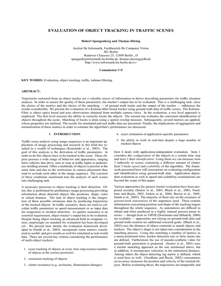
EVALUATION OF OBJECT TRACKING IN TRAFFIC SCENES Robert Spangenberg and Thomas Döring Institut für Informatik, Fachbereich für Computer Vision HU Berlin Rudower Chaussee 25, 12489 Berlin , D spangenb@informatik.hu-berlin.de, thomas.doering@dlr.de http://www.informatik.hu-berlin.de/cv/ Commission V/5 KEY WORDS: Evaluation, object tracking, traffic, kalman filtering ABSTRACT: Trajectories extracted from an object tracker are a valuable source of information to derive describing parameters for traffic situation analysis. In order to ensure the quality of these parameters, the tracker’s output has to be evaluated. This is a challenging task, since the choice of the metrics and the choice of the matching — of ground truth tracks and the output of the tracker — influences the results considerably. We present the evaluation of a Kalman-filter based tracker using ground truth data of traffic scenes. The KalmanFilter is object space based and uses observations obtained from multiple camera views. In the evaluation, a two level approach is employed. The first level assesses the ability to correctly locate the objects. The second one evaluates the consistent identification of objects throughout the scene. Matching of tracks is done using a spatial overlap measure. Subsequently, several metrics are applied, whose properties are outlined. The results for simulated and real traffic data are presented. Finally, the implications of aggregation and normalization of these metrics in order to estimate the algorithm’s performance are discussed. 1 INTRODUCTION Traffic scene analysis using image sequences is an important application of image processing and research in this field has resulted in a wealth of techniques (Kastrinaki et al., 2003). The goal of this analysis is the derivation of traffic parameters. In order to do this objects have to be tracked in the scene. These objects possess a wide range of behavior and appearance, ranging form vehicles that drive, turn or stop at traffic lights to pedestrians strolling around. Often a multitude of objects is present at the same time and due to the restrictions in camera placement they tend to occlude each other in the image sequence. The coaction of these conditions mentioned turn the analysis of such scenes into challenging task. A necessary precursor to object tracking is their detection. Often, this is performed by preliminary image processing providing information about detected objects like positions, shape, color or salient features. The task of object tracking is the integration of these possible erroneous data by producing trajectories of the tracked objects. In traffic scenarios, these are used to calculate traffic parameters as speed measurement or as input data for congestion or incident detection. As quality assurance is an essential requirement, object tracker’s output has to be evaluated. Despite being object tracking an advanced field in computer vision, surprisingly no standard for evaluation has been developed yet. We present here shortly the evaluation framework developed in (Smith et al., 2005), incorporate some metrics considered as useful, and give results as well for simulated as real-world data. There are several key criteria considering the performance of multi-object trackers: 1. exact tracking of objects at every time step (correct number of objects at the correct positions) 2. consistent tracking of objects 3. clutter resistance (e.g. occlusion, illumination changes) 4. exact estimation of application-specific parameters 5. the ability to work in real-time despite a large number of tracked objects Item 4 deals with application-independent evaluation. Item 1 considers the configuration of the objects at a certain time step and item 2 their identification. Using them we can measure item 3 indirectly in scenes containing a different amount of clutter. Item 5 treats speed and scalability of the algorithm. The framework presented here will concentrate on evaluating configuration and identification using ground-truth data. Application dependent evaluation as well as speed and scalability examinations are beyond the scope of this paper. Various approaches for generic tracker evaluation have been proposed recently (Senior et al., 2001, Black et al., 2003, Needham and Boyle, 2003, Erdem et al., 2004, Brown et al., 2005, Smith et al., 2005). The majority of them rely on the existence of ground-truth annotations of the sequences used. These contain information concerning position and shape of the tracking targets throughout the whole sequence. As annotations are difficult to obtain and often produced in a highly manual process prone to errors — though tools as ViPER (Doermann and Mihalcik, 2000) are available — approaches not relying on ground-truth data and ground truth creation are additional research goals. (Black et al., 2003) uses the distance of object centroids to match objects and trackers. The object’s shape is not taken into consideration in the matching process. Using this matching a number of metrics as a mean positional error, tracker detection rate or false alarm rate are defined. Furthermore the use of pseudo-synthetic video for ground-truth generation is proposed. (Senior et al., 2001) uses a similar matching approach as the one mentioned above, but in addition, it incorporates velocities in the minimized distance. Among others the object detecting lag metric is defined, which is used here as well. (Needham and Boyle, 2003) concentrates on accuracy measures for position and velocity of the tracked objects. Before evaluating those, the trajectories are temporally and spatially aligned to the ground truth to purge the influence of constant time and/or positional displacements. (Erdem et al., 2004) proposes tracking metrics without the need of ground-truth and validates them in different scenarios. The approach in (Brown et al., 2005) is the most related to the one presented here. It uses a spatial overlap measure to match the trajectories in a two-level process. Some of the derived metrics for configuration and identification share the same philosophy as the work of (Smith et al., 2005), but there are several distinctions. 2 PRESENTATION AND DISCUSSION OF THE WORK OF SMITH ET. AL In this chapter we present and discuss the basic concepts of evaluation framework developed in (Smith et al., 2005). The notation is therefore identical to the referred paper. We refer to objects or targets as ground truth objects (GT ). Tracker outputs are referred to as estimates. Coverage Test To examine whether tracking is successful at a certain time step a spatial overlap measure is used. It is based on the harmonic mean of the recall ρ and precision ν measures stemming from the field of information retrieval (Baeza-Yates and Ribeiro-Neto, 1999). If the harmonic mean exceeds a defined threshold, tracking is considered to be successful and the coverage test is passed. This notion of tracking weighs the errors made by over- or underestimating the shape of an object equally. Another possibility would be to use the so called E-measure (van Rijsbergen, 1979): E =1− 1+b 1 ν + 2 b2 ρ (1) This measure is a parametrized form of the inverse harmonic mean, allowing the user to specify its preferences. For b = 1 is equal to the inverse harmonic mean. Values greater than one indicate a stronger interest in precision than recall while values lower than 1 indicate the opposite. Matching Process Based on this test, a two level matching process is executed. The first level considers configuration and is evaluated at every frame. An association between ground truth objects and estimates is thereby established if the coverage test is passed, i.e. the ground truth object is tracked by the estimate at this frame. The second level considers identification, looking at the whole sequence, using the matching of the first level as input. Another possibility for matching is followed by (Porikli, 2004). There, markov-chains models are constructed out of ground-truth tracks and estimates. The probability calculated that one chain model generates the other one is used as a distance measure. Instead of the bottom-up process applied in (Smith et al., 2005) a one-level matching is used which might provide a better similarity measure at the cost of a more complex evaluation and the lack of information on configuration errors. The results of the matching process enable the calculation of the following configuration/identification errors and metrics. Configuration Errors and Metrics The first possible configuration error (cf. figure 1) is caused by a system creating an output that does not exist (false positive, FP). On the other side it may not detect a present object (false negative, FN). Furthermore the system may track an object with multiple estimates (multiple tracker, MT). One estimate may also track more than one object (multiple object, MO), which is an error as well. Those errors are counted in each frame and normalized by the number of ground truth objects present. This accounts for the increasing difficulty of scenes containing more objects. 5 3 1 2 4 b a LE FP FN d e c MT MO Figure 1: Types of configuration errors: localization error (LE), false positive (FP), false negative (FN), multiple tracker (MT), multiple object (MO) — estimates are shown as dashed rectangles and numbered, ground truth objects are labeled with characters GT 1 2 3 FIT a b c FIO Figure 2: Identification errors: falsely identified tracker (FIT), falsely identified object (FIO) Identification Errors and Metrics Two types of identification errors are considered in (Smith et al., 2005) (cf. 2) Firstly, it is possible that the system tracks a ground truth object GT j at a certain point by another estimate Ek , while it is tracked for the longest time by estimate Ei , which identifies it. In the example, object a is tracked by estimate 2, while it was previously identified by estimate 1. This type of error is referred to as a falsely identified tracker FIT. The second error occurs if a Ei tracks a GT j at first but than locks on to another GT k (estimate 3 in figure 2, called falsely identified object — FIO). The tracker swaps from one target to an other, a common failure in object trackers. Of further interest is the rate of consistency achieved in object tracking. Object purity (OP) is the rate of successful identifications of an GT j by the estimate Ei , that identifies it. A high object purity means that this object is tracked continuously by one tracker at the indicated rate. Tracking purity (TP) is the ratio of successful identifications of an Ei that identified a GT j . A higher TP value means that less tracker swapping occurs, with it being completely absent at the tracker purity of 1. 3 EXTENSIONS AND OWN IMPLEMENTATION In this chapter the extensions and adaptions in our re-implementation of the framework proposed by (Smith et al., 2005) are highlighted. (Smith et al., 2005) uses shapes in image space to evaluate the tracking. As we want to evaluate multi-camera-tracking as well, we used ortho-projected shapes of the tracked objects as input for the coverage test. Therefore, the interior and exterior orientation of the cameras has to be known. In a multi-camera setup, weak exterior and/or interior orientation should be avoided, as the errors introduced could lead to failure of the evaluation. A advantage of this approach is that spatial overlap measures have a clear interpretation and there is no influence caused by occlusion. Configuration Metrics The location error LE is considered to be worth being determined as well. It is defined as the centroid X LEtj = d(GT tj , Eit ) Eit tracks GT tj LE = 1 n 1 LE = n ′ X t X t X t,c 1 t max(NGT , 1) NGT LEtj (3) LEtj (4) j=1 X 4 EXPERIMENTS AND RESULTS (2) This section is organized as follows: At first the tracking algorithm is presented briefly. The generation of simulation data and a discussion of the simulation results follows. This includes reasoning about correct normalization and aggregation of the metrics as well. Finally, results with real traffic data are presented. t,c 1 t,c , 1) max(NGT NGT j=1 Figure 3: Localization error as additional configuration metric — t being NGT being the number of ground truth objects present at t,c the number of tracked ground truth objects, d(·, ·) instant t, NGT the euclidean distance of the centroids of arguments and n the number of frames 4.1 The Tracking Algorithm There are various perceptions of the idea object tracking. Some conceive this as a totality of sensor network, sensor calibration, data acquisition, object recognition and chronological object mapping, others as a aggregation of some of these modules. In this paper object tracking is referred to as the last one: chronological object mapping (see figure 5). ti ntracked (j) , CVj = nj ( ODLj = 1 CV = NGT X NGT X ODLj ∆t Image 1 Image 2 Image 3 Object 1 Object 1 Object 1 Object 2 Object 2 Object 2 Object 3 Object 3 Object 3 Object 4 Object 4 Object 4 (5) , Eij exists , otherwise (6) NGT j=1 ti+2 j=1 tf irst (GT j , Eij ) − tstart (GT j ) 0 1 ODL = NGT CVj ti+1 (7) Figure 4: Additional identification metrics — calculation and normalization: ntracked (j) is the number frames GT j is tracked, nj the number of frames GT j exists, tstart (·) is the start time, tf irst (·, ·) is the first time, the arguments pass the coverage test, Eij is the estimate that identifies GT j , ∆t is the mean difference of two successive frames, NGT the number of ground truth tracks and NE the number of estimates In our evaluation tests the tracking algorithm suggested in (Döring, 2005) is used. It consists basically of the prediction algorithm Kalman Filter, an object mapping routine based on significance tests and several filtering and memory based techniques to minimize effects like occlusion, clustering or segmentation. Every image k of a sensor used provides position data for every object Rk . The aim is to map the belonging measurement – the observation – to an existing object and update its state values describing the object itself, e.g. position or shape (see figure 6), based on the measured data. Rk ªXk º «Y » « k» « Zk » « » ¬« tk ¼» Tracking distance between a ground truth object and the estimate(s) that it is tracked by in a frame, i.e. the mean of the distances to all estimates that pass the coverage test. If no estimate is associated as the object is not tracked, the localization error is zero. Normalization by the number of objects present at this time seems natural (LE in figure 3), but as we will see later is not optimal. A better normalization can be achieved by the number of objects ′ t,c (LE ). tracked at this time NGT Figure 5: Tracking principle ai (t ) Oi (t ) ª si (t ) º « v (t ) » « i » «¬ ai (t ) »¼ wvi (t ) wt w 2 si (t ) wt 2 Figure 6: Mathematical view Identification Metrics In addition to the purity measure for ground truth objects, the metric coverage CVj of a ground truth object GT j is taken into consideration (this is a widespread measure cf. for example (Black et al., 2003)). It is defined as the number of frames GT j is tracked to the total number of frames it occurs in, giving an overview of the difficulty imposed by the object to be tracked. It thereby stresses the importance of tracking an object, not continuous tracking as the object purity does. Finally we define the object detection lag (ODL) (cf. (Senior et al., 2001)) of an GT j as the time difference between the first appearance of the object and the point in time the tracking is started by the estimate Eji that identifies it. That means, it is not the first time it is being tracked by some Ek but the first time it is tracked by Eji . If GT j was never tracked, in this case the lag is set to zero as the object was never detected. Normalization is done by dividing the values by the mean time difference of two consecutive frames. This is done in order to enable a fair comparison of tracking algorithms run at different frame rates. The tracking process described in (Döring, 2005) provides the possibility of pseudo-fusing data acquired from different sensors. The algorithm is independent from the sensor providing the data as long as it is acquired in one joint coordinate system (see figure 7). Normally this is achieved by transforming the measured image coordinates into the object coordinate system using calibration and exterior orientation parameters. The quality of the resulting objects state is highly correlated to the quality of the observation accuracy values provided by the cameras and their transformation algorithms. Thus, it is important to take ground resolution and camera quality into account. 4.2 Simulation The simulation is based on traffic data generated by the software VISSIM, which uses the psycho-physical driver model developed Sensor 1 Observation Sensor 2 Observation t2 Observation 1. If t equals shutter time, get object coordinates xi from traffic simulation Observation t1 Observation Observation t3 Observation t4 Observation Figure 7: Pseudo data fusion 2. Test for each object whether it is visible for the camera by projection on the image plane and a check for static occlusion. If the test is passed, then add object to the objects seen by the camera and transform coordinates into pixel coordinates 3. For each seen object sensor noise R is added R ∼ N (0, σR ) to its chip location 4. An object xi is detected by the image processing, if pd > D ∼ U (0, 1) . 5. Two objects xi , xj are clustered, if the euclidean distance d(xi , xj ) < C ∼ N (0, σc ). 6. An object xi is segmented, if ps > S ∼ U (0, 1). For every segmented object two new objects will be created, their positions being xi with N (0, σa ) noise added. Figure 8: Simulated crossing with camera positions 7. Transformation into world coordinates in (Wiedemann, 1974). As it models driver behavior, physical restrictions to vehicle movement and the influence of crossings, different types of vehicles, traffic lights, etc., a realistic simulation of a crossing is possible (see figure 8). They traffic simulation’s output, consisting of lists of object positions and shapes in world coordinates at every simulated time step, is used as input for a simplistic simulation of the image acquisition and processing steps which occur in real world scenes. Figure 9: Simulated image acquisition processing for a virtual camera Image acquisition and processing The simulation positions virtual cameras in the virtual scene that process the object positions created by the traffic simulation (figure 9). Every camera is characterized by interior and exterior orientation, frame rate, jitter, sensor noise and presence of static occlusions in its field of view (e.g. traffic lights, signs, street lights). Image processing is modeled as a detection process including clustering and/or segmentation. This models dynamic occlusions to a certain extent, as they manifest them self in clustering and/or segmentation in the image processing step. The strength of the approach lies in the ease of definition of a multi-camera setup and the possibility to study the influence of certain parameters on the tracking performance before starting a possibly costly campaign to acquire data on a real-world crossing. Trackers, operating on images and not on world coordinates, would need a sufficiently realistic rendering of the traffic data, which would complicate the simulation considerably. (b) identification metrics Experiments The experiments were conducted with a sequence of 153 vehicles (cars, trucks, buses, bikes) of 300 seconds length. In the basic setup one camera (camera 1) is used with a frame rate of 10 Hz looking at the scene (field of view in figure 8). Its parameters for simulated image acquisition and processing are image noise σR = 2px, detection probability pd = 0.95, cluster distance σc = 5px, segmentation probability ps = 0.005 and segmentation distance σa = 20px. These values shall serve as a baseline, defining not ideal, but very good environmental conditions and nearly perfect image processing. The tracker parameters were initialized with to standard values and the maximum speed expected was vmax = 70km/h. Results The results show a good but not superior performance of the algorithm. Especially high values for false negatives on the one hand and a low coverage and bad object purity on the other mean σ FP 0.039 0.002 FN 0.213 0.004 MT 0.032 0.004 MO 0.075 0.002 LE 0.343 0.009 (a) configuration metrics mean σ FIT 0.104 0.014 FIO 0.087 0.007 ODL 24.720 1.864 OP 0.657 0.008 TP 0.908 0.010 CV 0.740 0.010 Table 1: results simulation (mean of 10 simulations) made a further inspection necessary. The identified cause turned out to be the algorithm’s tendency to cluster objects when the are driving in parallel. This initialization issue should be resolved using additional features like color cues. In further experiments different parameters like image noise, detection rate or clustering rate were varied (figure 13) to study their influence. In addition, this was done to check whether the variation of the metrics was consistent with the expectations, which was the case if the frame rate was varied. Tracking performance degrades progressively with a lower frame rate with 10 Hz being a good compromise between effort and results. In general the interpretation of tracking purity TP is difficult. A decrease in this metric would be expected if the performance of the tracking algorithm gets worse, but at least for the tested tracker, it sometimes increases with degradation of overall performance. This is due to the fact that the tracker does not predominantly swap targets, rather than loosing them and then a reinitialization is triggered. Aggregation and normalization While varying the frame rate, the mean of the object detection lag ODL showed abnormal increase. Looking at a histogram of one pass in figure 11 it can clearly be seen that some outliers with a very high object detection lag render the mean misleading. The median gives a better aggregate estimate of the overall detection lag. The other deviation from the expected values occurred at the localization error LE. It decreased as the detection rate fell (figure 13(b)). Normalization can be improved to prevent this behavior. As ground truth objects that are not tracked at a time step have 1.0 0.8 0.6 0.4 CV OP TP 0.2 0.0 10 20 Framerate 30 40 Figure 15: Influence of shadow inclusion on shape centroid: green — reference, red — output of image processing 1 Figure 10: Influence of framerate: Coverage and purity metrics ip 1 ip 2 FP 0.46 0.55 FN 0.68 0.71 MT 0.007 0.05 MO 0.004 0.012 LE 0.67m 0.35m ′ LE 2.01m 1.66m (a) configuration metrics 40 median mean tracks 30 FIO 0.07 0.05 med(ODL) 5.00s 10.02s OP 0.23 0.18 TP 0.41 0.36 CV 0.31 0.24 (b) identification metrics 20 Table 2: results traffic scene: ip1 — image processing 1, ip2 — image processing 2, med(·) is the median 10 0 0 20 40 60 ODL in frames 80 Figure 11: Histogram object detection lag a localization error of zero and the sum of all localization errors is normalized by the number of all present ground truth objects, situations with very bad tracking (for example only 1 out of 10 objects present is tracked) lead to a localization error of nearly ′ 0. An improved normalization is given by LE (figure 13(b) and t,c 13(c)). The normalization factor is NGT , the sum of all tracked ground truth objects. Another possibility is the the introduction of a penalty term for every uncovered trajectory. This would create another parameter in the evaluation process, which in its pure form has the advantage that it only depends on one parameter, the coverage threshold tC . 4.3 ip 1 ip 2 FIT 0.09 0.52 Traffic Data Performance on real traffic data is shown by a sequence of grayvalue images taken at a crossing with dense traffic (figure 12). It was recorded with 6Hz at challenging exterior conditions. The length of the sequence is 600 frames at a resolution of 1024x1024 pixels. In total, 134 vehicles appear in the scene. Reference tracks were created by manual annotation (figure 14(a)). In some parts of the scene, vehicle localization seems to be difficult even for humans, leading to a high centroid variance. Using the framework, the combination of two different image processing systems and the Kalman filter was evaluated (result tracks in figure 14(b) and 14(c)). Due to the quality of the reference data, an absolute measurement of tracker performance was not possible. Reference data would have to be improved/and or filtered to allow this. In comparison, results of combination 1 are clearly superior (see figure 14(b)), as it produces longer tracks, less outliers and has better coverage. However, the results of the metrics do not reflect this completely (table 2). Reported values for false negatives are too high, the ones for object purity and coverage are too low, possibly due to the quality of the reference data. Interestingly the localization error is a lot higher for the better combination. A closer look at the object detection results revealed that image processing 1 included significant parts of the vehicle shadows in the reported shapes leading to a increased localization error and a problem in the matching process, as spatial overlap was insufficient. The use of a spatial alignment as suggested in (Needham and Boyle, 2003) is not possible, as the visibility of shadows is dependent in the orientation and shape of the vehicles and therefore not constant in the scene (see figure 15). Reliable shadow removal algorithms rely on color information (for a review article see (Prati et al., 2003)) and therefore cannot be applied. Thus, using the framework to gray-level sequences poses restrictions to the validity of the metrics in the presence of shadows. 5 CONCLUSIONS We presented a framework for the evaluation of object tracking algorithms in a multi-camera setup. Emphasis was especially put on the incorporation of additional metrics into an existing framework. Validation was achieved by using traffic simulations and real traffic scenes. Finally the implications of aggregation and normalization were discussed. REFERENCES Baeza-Yates, R. and Ribeiro-Neto, B., 1999. Modern Information Retrieval. First edn, Addison-Wesley. Black, J., Ellis, T. and Rosin, P., 2003. A novel method for video tracking performance evaluation. In: Joint IEEE Int. Workshop on Visual Surveillance and Performance Evaluation of Tracking and Surveillance (VS-PETS). Figure 12: Traffic scene Brown, L. M., Senior, A. W., li Tian, Y., Connell, J., Hampapur, A., Shu, C., Merkl, H. and Lu, M., 2005. Performance evaluation of surveillance systems under varying conditions. In: IEEE Int’l 1.0 1.0 LE FN FP 0.8 1.0 LE’ LE FP FN 0.8 0.6 0.6 0.6 0.4 0.4 0.4 0.2 0.2 0.2 0.0 0 5 10 σR 15 20 0.0 0.5 0.6 0.7 pd 0.8 0.9 0.0 1.0 1.0 0.8 0.8 0.8 0.6 0.6 0.6 0.4 0.4 TP CV OP 0.2 5 10 σR 20 15 30 40 50 0.4 TP CV OP 0.2 20 σc (c) 1.0 0 10 (b) (a) 0.0 LE’ LE FN FP 0.8 0.0 0.5 0.6 0.7 pd 0.8 0.9 TP CV OP 0.2 0.0 10 (e) (d) 20 σc 30 40 50 (f) Figure 13: Influence of noise (left), detection probability (middle) and clustering rate (top) in simulation: top — configuration metrics, bottom — identification metrics (a) Reference tracks (b) estimate tracks image processing 1 (c) estimate tracks image processing 2 Figure 14: ortho-projections of reference tracks and estimates Workshop on Performance Evaluation of Tracking and Surveillance, Colorado. Performance Evaluation for tracking and Surveillance (PETS, ECCV), Prague. Doermann, D. and Mihalcik, D., 2000. Tools and Techniques for Video Performances Evaluation. In: ICPR, Vol. 4, pp. 167–170. Prati, A., Mikic, I., Trivedi, M. M. and Cucchiara, R., 2003. Detecting moving shadows: Algorithms and evaluation. IEEE Trans. Pattern Anal. Mach. Intell. 25(7), pp. 918–923. Döring, T., 2005. Verfolgung von Verkehrsobjekten aus verschiedenen Kameraperspektiven. Diplomarbeit, Universität Stuttgart - ifp. Erdem, C. E., Sankur, B. and Tekalp, A. M., 2004. Performance measures for video object segmentation and tracking. IEEE Transactions on Image Processing 13(7), pp. pp. 937–951. Kastrinaki, V., Zervakis, M. E. and Kalaitzakis, K., 2003. A survey of video processing techniques for traffic applications. Image Vision Comput. 21(4), pp. 359–381. Needham, C. J. and Boyle, R. D., 2003. Performance evaluation metrics and statistics for positional tracker evaluation. In: ICVS, pp. 278–289. Porikli, F., 2004. Trajectory distance metric using hidden markov model based representation. In: 6th International Workshop on Senior, A., Hampapur, A., Tian, Y.-L., Brown, L., Pankanti, S. and Bolle, R., 2001. Appearance models for occlusion handling. In: Second International workshop on Performance Evaluation of Tracking and Surveillance Systems in conjunction with CVPR’01. Smith, K., Gatica-Perez, D., Odobez, J.-M. and Ba, S., 2005. Evaluating multi-object tracking. In: Proc. IEEE Conf. on Computer Vision and Pattern Recognition, Workshop on Empirical Evaluation Methods in Computer Vision (CVPR-EEMCV), San Diego. van Rijsbergen, C. J., 1979. Information Retrieval. Butterworth. Wiedemann, R., 1974. Simulation des Straßenverkehrsflusses. Schriftenreihe des Institutes für Verkehrswesen der Universität Karlsruhe, Heft 8.

