MECHANICAL FMC TECHNIQUES FOR REMOVING IMAGE BLUR IN DIGITAL AERIAL CAMERAS
advertisement
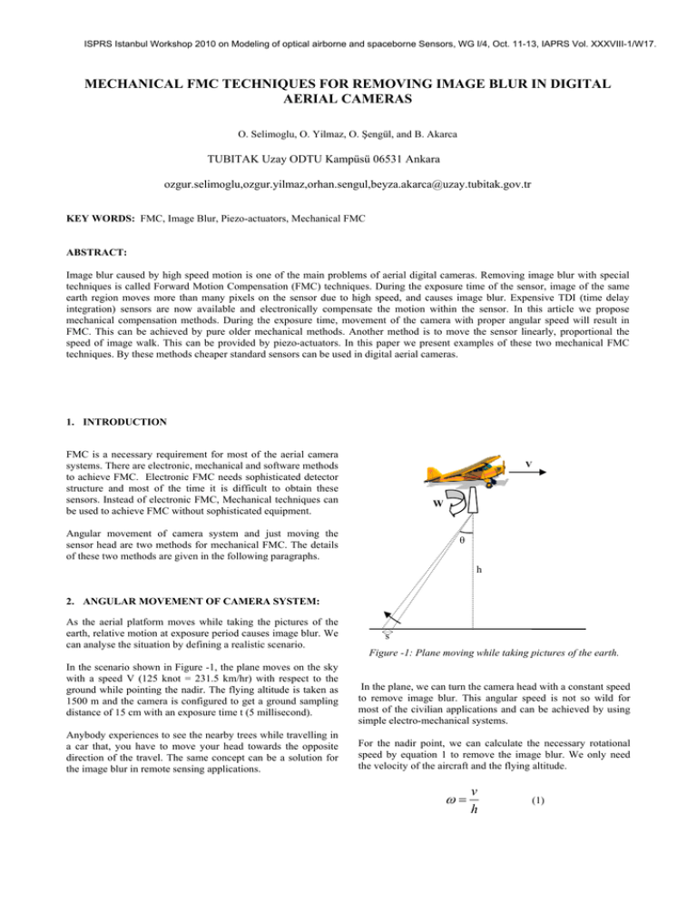
ISPRS Istanbul Workshop 2010 on Modeling of optical airborne and spaceborne Sensors, WG I/4, Oct. 11-13, IAPRS Vol. XXXVIII-1/W17. MECHANICAL FMC TECHNIQUES FOR REMOVING IMAGE BLUR IN DIGITAL AERIAL CAMERAS O. Selimoglu, O. Yilmaz, O. Şengül, and B. Akarca TUBITAK Uzay ODTU Kampüsü 06531 Ankara ozgur.selimoglu,ozgur.yilmaz,orhan.sengul,beyza.akarca@uzay.tubitak.gov.tr KEY WORDS: FMC, Image Blur, Piezo-actuators, Mechanical FMC ABSTRACT: Image blur caused by high speed motion is one of the main problems of aerial digital cameras. Removing image blur with special techniques is called Forward Motion Compensation (FMC) techniques. During the exposure time of the sensor, image of the same earth region moves more than many pixels on the sensor due to high speed, and causes image blur. Expensive TDI (time delay integration) sensors are now available and electronically compensate the motion within the sensor. In this article we propose mechanical compensation methods. During the exposure time, movement of the camera with proper angular speed will result in FMC. This can be achieved by pure older mechanical methods. Another method is to move the sensor linearly, proportional the speed of image walk. This can be provided by piezo-actuators. In this paper we present examples of these two mechanical FMC techniques. By these methods cheaper standard sensors can be used in digital aerial cameras. 1. INTRODUCTION FMC is a necessary requirement for most of the aerial camera systems. There are electronic, mechanical and software methods to achieve FMC. Electronic FMC needs sophisticated detector structure and most of the time it is difficult to obtain these sensors. Instead of electronic FMC, Mechanical techniques can be used to achieve FMC without sophisticated equipment. V W Angular movement of camera system and just moving the sensor head are two methods for mechanical FMC. The details of these two methods are given in the following paragraphs. θ h 2. ANGULAR MOVEMENT OF CAMERA SYSTEM: As the aerial platform moves while taking the pictures of the earth, relative motion at exposure period causes image blur. We can analyse the situation by defining a realistic scenario. In the scenario shown in Figure -1, the plane moves on the sky with a speed V (125 knot = 231.5 km/hr) with respect to the ground while pointing the nadir. The flying altitude is taken as 1500 m and the camera is configured to get a ground sampling distance of 15 cm with an exposure time t (5 millisecond). Anybody experiences to see the nearby trees while travelling in a car that, you have to move your head towards the opposite direction of the travel. The same concept can be a solution for the image blur in remote sensing applications. s Figure -1: Plane moving while taking pictures of the earth. In the plane, we can turn the camera head with a constant speed to remove image blur. This angular speed is not so wild for most of the civilian applications and can be achieved by using simple electro-mechanical systems. For the nadir point, we can calculate the necessary rotational speed by equation 1 to remove the image blur. We only need the velocity of the aircraft and the flying altitude. ω= v h (1) ISPRS Istanbul Workshop 2010 on Modeling of optical airborne and spaceborne Sensors, WG I/4, Oct. 11-13, IAPRS Vol. XXXVIII-1/W17. If we want FMC for all the image points, we need to calculate the necessary rotational speed for those corresponding points. As a result of calculations we conclude that different rotational speeds are necessary for different points on the ground. The necessary rotational speed is calculated by using the equation 2. ω= θ − arctan(tan θ − t vt ) h (2) The necessary angular speed needed for different angular position is shown in the Figure-2. As shown from the graph, necessary angular velocity reduces with the angle. Figure -3: Remaining image blur with respect to the angle from nadir. From the mechanical point of view, moving all the camera structure can induce vibration problems. So, if the camera structure is not rigid enough, instead of moving the entire camera, a mirror can be added to the system. The camera will look to the mirror and see the ground from this mirror. If we rotate the mirror, it will have the same effect of rotating the camera with respect to the ground. 3. LINEAR MOVEMENT OF THE SENSOR: Figure -2: Required rotational speed for FMC Harmonic motion is needed to get prepared to the next shot. The exposure time is a very small fraction of the time between two shots. In the remaining time, the camera should return to the initial position again and at the next exposure time it should have the proper angular speed. This movement is easily can achieved by using a constant rotation speed cam assembly. By giving proper shape to the cam, we can easily rotate the camera body with a proper speed profile. An inherent behaviour of this kind of FMC is that a complete FMC is not possible. Even if we can achieve a complete FMC for the nadir point, for the other ground points it is not possible. But the remaining image blur (smearing) may be acceptable depending on the FOV of the objective and the necessary compensation for the application. In the Figure-3, we have shown that which angular deviation from nadir point has which amount of image blur. From simulations we conclude that this technique gives satisfactory results for small FOV systems. If we put a criteria such that image blur should not exceed half of a pixel, than the objective that we will be used should not have a full field of view greater than 60 degrees. Absolute FMC is achieved at the nadir and FMC error increases with the angular deviation. Without moving all the camera structure, it is possible to move only the sensor part linearly towards the direction of image walk. In this method, only a small linear movement is sufficient to remove image blur. To get FMC, during exposure, a constant speed linear movement is necessary. The required motion can be obtained by using small linear displacement actuators such as piezo actuators. To achieve a uniform movement, it is better to start the movement a little earlier than the exposure. Necessary focal plane movement speed can be calculated by Equation-3. V fp = v * f h (3) If we consider the same scenario used in the first method, the only necessary variable to calculate speed of the focal plane movement is the focal length. By selecting the focal length as 70 mm which is an acceptable focal length, than the required speed is only 3 mm/sec. The movement should start a little earlier than the exposure and finish a little time later. If we assume the movement starts an exposure duration earlier and finish an exposure duration later, than the actuator should move totally 3 exposure durations. If we choose the exposure time 5 millisecond, than only 45 micron movement range is necessary. This is in the range of simple piezo actuators. ISPRS Istanbul Workshop 2010 on Modeling of optical airborne and spaceborne Sensors, WG I/4, Oct. 11-13, IAPRS Vol. XXXVIII-1/W17. The same movement should be repeated for every shot. To get prepared to the next shot, the sensor should move back to the original position after the exposure time. In this configuration, the same focal plane movement speed is necessary for nadir and off axis points. As a result, a complete FMC can be achieved. 4. PROBLEMS PERSPECTIVE CAUSED BY DISTORTION AND Mathematical models assume perfect optics and perfect nadir pointing. But the situation is not always like this. Optics has always some distortion. This optical distortion may prevent FMC in the aerial photography. Distortion is the changing effective focal length with the angle. As seen from the Equation-3, focal length is a parameter for the FMC generating movement. Therefore if the distortion is large, a successful FMC is not possible by moving the focal plane (method 2). The first method will not be affected from the distortion because it is not related to the focal length. In some applications objective lenses should be placed with an angle from the vertical. The most encountered application is large FOV imaging. To achieve large FOV, multiple lenses should be accommodated in the camera. Every lens will look different directions and cover different land areas. This will cause FMC degradation because objective lenses are optimised for nadir pointing photography. If the camera look with an oblique angle, than there are perspective problems. Since all the pixels do not correspond to the same ground distance coverage, it is not possible to achieve a complete FMC by using simple methods. 5. CONCLUSION In this paper two different mechanical FMC techniques are discussed. Both of the methods have inherent strong and weak sides. For multiple objective systems, single cam actuator is enough if we use the first method. By moving the actuator, all the cameras in the camera system will experience image blur reduction. If we use second method with multiple objective systems, than every detector should have its own actuator. While the second method is more successful to achieve FMC, the first method is simpler. In the high performance expensive camera systems, multiple focal plane actuators can be used where the price is not the main parameter. For low cost systems, adding FMC by using first technique is easy and will significantly reduce the image blur to an acceptable level. 6. REFERENCES 1. Sandau, R. (2010). Digital Airborne Camera, Introduction and Technology. Springer. 2. Recon/optical Inc. Electro-optical imaging array with motion compensation. 1991.(PCT/US1991/008649)
