AN IMPROVED SIMPLIFICATION ALGORITHM OF 3D TERRAIN VISUALIZATION MODEL
advertisement

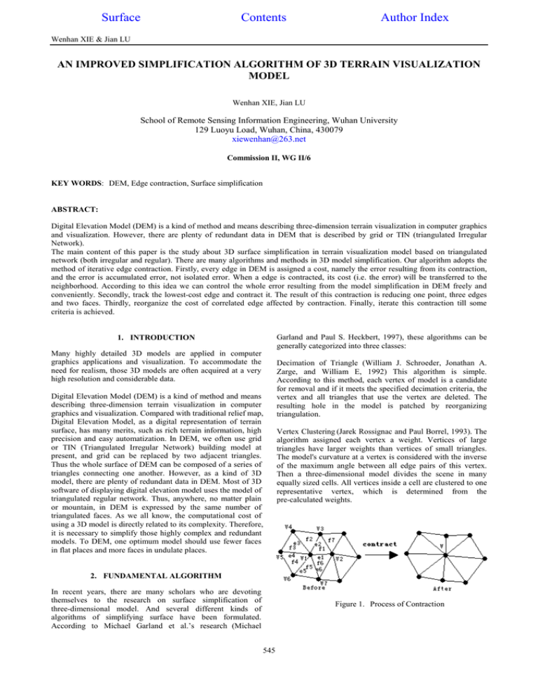
Surface Contents Author Index Wenhan XIE & Jian LU AN IMPROVED SIMPLIFICATION ALGORITHM OF 3D TERRAIN VISUALIZATION MODEL Wenhan XIE, Jian LU School of Remote Sensing Information Engineering, Wuhan University 129 Luoyu Load, Wuhan, China, 430079 xiewenhan@263.net Commission II, WG II/6 KEY WORDS: DEM, Edge contraction, Surface simplification ABSTRACT: Digital Elevation Model (DEM) is a kind of method and means describing three-dimension terrain visualization in computer graphics and visualization. However, there are plenty of redundant data in DEM that is described by grid or TIN (triangulated Irregular Network). The main content of this paper is the study about 3D surface simplification in terrain visualization model based on triangulated network (both irregular and regular). There are many algorithms and methods in 3D model simplification. Our algorithm adopts the method of iterative edge contraction. Firstly, every edge in DEM is assigned a cost, namely the error resulting from its contraction, and the error is accumulated error, not isolated error. When a edge is contracted, its cost (i.e. the error) will be transferred to the neighborhood. According to this idea we can control the whole error resulting from the model simplification in DEM freely and conveniently. Secondly, track the lowest-cost edge and contract it. The result of this contraction is reducing one point, three edges and two faces. Thirdly, reorganize the cost of correlated edge affected by contraction. Finally, iterate this contraction till some criteria is achieved. Garland and Paul S. Heckbert, 1997), these algorithms can be generally categorized into three classes: 1. INTRODUCTION Many highly detailed 3D models are applied in computer graphics applications and visualization. To accommodate the need for realism, those 3D models are often acquired at a very high resolution and considerable data. Digital Elevation Model (DEM) is a kind of method and means describing three-dimension terrain visualization in computer graphics and visualization. Compared with traditional relief map, Digital Elevation Model, as a digital representation of terrain surface, has many merits, such as rich terrain information, high precision and easy automatization. In DEM, we often use grid or TIN (Triangulated Irregular Network) building model at present, and grid can be replaced by two adjacent triangles. Thus the whole surface of DEM can be composed of a series of triangles connecting one another. However, as a kind of 3D model, there are plenty of redundant data in DEM. Most of 3D software of displaying digital elevation model uses the model of triangulated regular network. Thus, anywhere, no matter plain or mountain, in DEM is expressed by the same number of triangulated faces. As we all know, the computational cost of using a 3D model is directly related to its complexity. Therefore, it is necessary to simplify those highly complex and redundant models. To DEM, one optimum model should use fewer faces in flat places and more faces in undulate places. Decimation of Triangle (William J. Schroeder, Jonathan A. Zarge, and William E, 1992) This algorithm is simple. According to this method, each vertex of model is a candidate for removal and if it meets the specified decimation criteria, the vertex and all triangles that use the vertex are deleted. The resulting hole in the model is patched by reorganizing triangulation. Vertex Clustering (Jarek Rossignac and Paul Borrel, 1993). The algorithm assigned each vertex a weight. Vertices of large triangles have larger weights than vertices of small triangles. The model's curvature at a vertex is considered with the inverse of the maximum angle between all edge pairs of this vertex. Then a three-dimensional model divides the scene in many equally sized cells. All vertices inside a cell are clustered to one representative vertex, which is determined from the pre-calculated weights. 2. FUNDAMENTAL ALGORITHM In recent years, there are many scholars who are devoting themselves to the research on surface simplification of three-dimensional model. And several different kinds of algorithms of simplifying surface have been formulated. According to Michael Garland et al.’s research (Michael Figure 1. Process of Contraction 545 IAPRS, VOLUME XXXIV, PART 2, COMMISSION II, Xi’an, Aug.20-23, 2002 Iterative Edge Contraction. Several algorithms about simplifying models are based on iteratively contracting edges (see Figure 1). The unique difference between these algorithms lies in that they have different criteria to contract an edge. Our simplifying algorithm is based on iterative edge contraction. According to this algorithm, every edge of model is assigned a cost (i.e. the error resulted from contracting). And the cost of edge can be divided into the costs of vertices forming this edge. Supposing v1 and v2 are two vertices of an edge (see Figure 1), and after contracting, v1 and v2 became the vertex v, then the cost v1 can be defined as, before and after contracting, the height difference that plane position (x1, x2) of v1 corresponds. The cost v2 has the same definition too. Naturally, the cost of edge is, the sum of the cost of v1 and the cost of v2 when an appropriate position of vertex v makes the sum minimize. To simplify the complexity of calculation, we often select v1 or v2 as the final position of v after contracting. Thus each edge contraction can reduce two faces (with the exception of the boundary of model). To the whole model, we first calculate all the costs of edges, and then select the edge of the minimum cost to contract, reorganize the triangulate network and its topology, and calculate the costs of the affected edges. Iterate above processes until meeting some criteria. Figure 2. 2D shading image of DEM of Sanxia Region Figure 3. Image of edge intensity 4. RELATED DETAILS 3. IMPROVED ALGORITHM 4.1 Restricted Conditions The cost of the algorithm mentioned above is isolated. Namely, each contraction is relevant to the costs of this iteration and this simplification is operated on the premise that the model obtained through previous iteration has no error. And most of algorithms based on iterative edge contraction don’t consider this factor. In fact, each simplifying model has error, and the error is the accumulative error. To DEM with continuous terrain, it is necessary to preserve its boundary when simplifying the model. However, if we directly apply the algorithm of edge contraction to DEM without any restricted conditions, the boundary of DEM will be shrunk. To preserve its original boundary shape, we can set the cost of boundary edge a maximum value. 4.2 Topological Structure Aiming at this condition, we put forward the improved algorithm. Compared with above algorithm, the new algorithm improves two facets: 1) The cost of each edge is accumulative. The cost is divided into two parts: one is the error brought from this contraction; another is the error resulted from previous contraction. The improved algorithm puts each contracting result into stacks, thus the vertices removed can be stored and when calculating the cost of edge, we can add the errors of historical vertices through stacks. The merit of this algorithm is that the model simplified has higher quality due to the real error and that the model can be controlled conveniently in order to achieve some need. When contracting edge, it is necessary for the algorithm to build topology for vertex, edge and face (i.e. triangle). Because our algorithm mainly discusses the case of triangulate network, we define the topology as follows (see figure 1): Relationship of topology Point to point Point to line Point to face Line to face Face to face 2) Further, different vertices have different weights. In DEM, not all the vertices are the same “important”. Generally speaking, the undulate areas (such as mountain) are more important than the flat areas (such as plain). We can view DEM as a special 2D image (See Figure 2), and then the undulate region can be regarded as the edge of image. According to this principle, we put edge intensity of vertex as its weight (See Figure 3). Example V1—v2, v3, v4, v5, v6, and v7 V1—e1, e2, e3, e4, e5, and e6 V1—f1, f2, f3, f4, f5 and f6 e1—f1 and f6 f1—f2, f6 and f7 Table 1. Topology structure of algorithm 4.3 Evaluating Quality (Li Zhilin, Zhu Qing, 2000) Several methods can be used to evaluate quality of model simplified. Among them, the method of Checking vertex is frequently used. This method first compares two height values (one is obtained from original model and the other is obtained from model simplified) of original grid vertices of DEM, and then calculates root mean square of error (RMSE) according to the error of each vertex. 546 Wenhan XIE & Jian LU Suppose the height of vertex of original model is Z k (k=1,2…n), after simplifying model, the height of vertex is Z k' , and then the evaluating formula is: σ DEM = Where ( 1 n ' ∑ Zk − Zk n k =1 ) 2 (1) σ DEM = RMSE of DEM n = the total number of vertices in DEM 5. EXPERIMENT AND CONCLUSION Figure 7. Model with 7084 vertices and 13846 faces This paper takes the DEM of region of Sanxia for example to illustrate the algorithm. The resolution of this DEM is 20.0m and this 3D model has 148347 vertices and 295120 faces. The original DEM is shown as Figure 4 and the original triangular network is shown as Figure 6. The simplified DEM (shown as Figure 5) has 7084 vertices and 13846 faces. According to experimental data, there is basically no difference between two DEM when the compressing ratio achieves five percent or so. REFERENCE Jarek Rossignac and Paul Borrel. 1993. Multi-resolution 3D approximations for rendering complex scenes. Modeling in Computer Graphics: Methods and Applications, pp. 455-4645. LI Zhilin, ZHU Qing, 2000. Digital Elevation Model, Press of Wuhan Tech University of Surveying and Mapping,3. Michael Garland and Paul S. Heckbert. Surface simplification using quadric error metrics. SIGGRAPH 97 Proc., pp.209-216. William J. Schroeder, Jonathan A. Zarge, and William E. Lorensen. Decimation of triangle meshes. SIGGRAPH ’92 Proc., 26(2).pp.65-70. Figure 4. Original DEM Figure 5. The simplified DEM Figure 6. Model with 148347 vertices and 295120 faces 547 IAPRS, VOLUME XXXIV, PART 2, COMMISSION II, Xi’an, Aug.20-23, 2002 548


