Document 11867309
advertisement
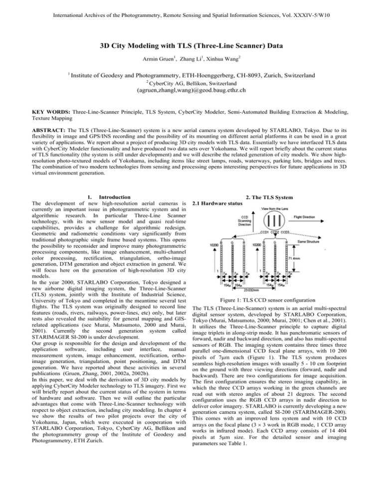
International Archives of the Photogrammetry, Remote Sensing and Spatial Information Sciences, Vol. XXXIV-5/W10 3D City Modeling with TLS (Three-Line Scanner) Data Armin Gruen1, Zhang Li1, Xinhua Wang2 1 Institute of Geodesy and Photogrammetry, ETH-Hoenggerberg, CH-8093, Zurich, Switzerland 2 CyberCity AG, Bellikon, Switzerland (agruen,zhangl,wang)@geod.baug.ethz.ch KEY WORDS: Three-Line-Scanner Principle, TLS System, CyberCity Modeler, Semi-Automated Building Extraction & Modeling, Texture Mapping ABSTRACT: The TLS (Three-Line-Scanner) system is a new aerial camera system developed by STARLABO, Tokyo. Due to its flexibility in image and GPS/INS recording and the possibility of its mounting on different aerial platforms it can be used in a great variety of applications. We report about a project of producing 3D city models with TLS data. Essentially we have interfaced TLS data with CyberCity Modeler functionality and have produced two data sets over Yokohama. We will report briefly about the current status of TLS functionality (the system is still under development) and we will describe the related generation of city models. We show highresolution photo-textured models of Yokohama, including items like street lamps, roads, waterways, parking lots, bridges and trees. The combination of two modern technologies from sensing and processing opens interesting perspectives for future applications in 3D virtual environment generation. 1. Introduction The development of new high-resolution aerial cameras is currently an important issue in photogrammetric system and in algorithmic research. In particular Three-Line Scanner technology, with its new sensor model and quasi real-time capabilities, provides a challenge for algorithmic redesign. Geometric and radiometric conditions vary significantly from traditional photographic single frame based systems. This opens the possibility to reconsider and improve many photogrammetric processing components, like image enhancement, multi-channel color processing, rectification, triangulation, ortho-image generation, DTM generation and object extraction in general. We will focus here on the generation of high-resolution 3D city models. In the year 2000, STARLABO Corporation, Tokyo designed a new airborne digital imaging system, the Three-Line-Scanner (TLS) system, jointly with the Institute of Industrial Science, University of Tokyo and completed in the meantime several test flights. The TLS system was originally designed to record line features (roads, rivers, railways, power-lines, etc) only, but later tests also revealed the suitability for general mapping and GISrelated applications (see Murai, Matsumoto, 2000 and Murai, 2001). Currently the second generation system called STARIMAGER SI-200 is under development. Our group is responsible for the design and development of the application software, including user interface, manual measurement system, image enhancement, rectification, orthoimage generation, triangulation, point positioning, and DTM generation. We have reported about these activities in several publications (Gruen, Zhang, 2001, 2002a, 2002b). In this paper, we deal with the derivation of 3D city models by applying CyberCity Modeler technology to TLS imagery. First we will briefly report about the current status of the system in terms of hardware and software. Then we will outline the particular advantages that come with Three-Line-Scanner technology with respect to object extraction, including city modeling. In chapter 4 we show the results of two pilot projects over the city of Yokohama, Japan, which were executed in cooperation with STARLABO Corporation, Tokyo, CyberCity AG, Bellikon and the photogrammetry group of the Institute of Geodesy and Photogrammetry, ETH Zurich. 2. The TLS System 2.1 Hardware status Figure 1: TLS CCD sensor configuration The TLS (Three-Line-Scanner) system is an aerial multi-spectral digital sensor system, developed by STARLABO Corporation, Tokyo (Murai, Matsumoto, 2000; Murai, 2001; Chen et al., 2001). It utilizes the Three-Line-Scanner principle to capture digital image triplets in along-strip mode. It has panchromatic sensors of forward, nadir and backward direction, and also has multi-spectral sensors of RGB. The imaging system contains three times three parallel one-dimensional CCD focal plane arrays, with 10 200 pixels of 7µm each (Figure 1). The TLS system produces seamless high-resolution images with usually 5 - 10 cm footprint on the ground with three viewing directions (forward, nadir and backward). There are two configurations for image acquisition. The first configuration ensures the stereo imaging capability, in which the three CCD arrays working in the green channels are read out with stereo angles of about 21 degrees. The second configuration uses the RGB CCD arrays in nadir direction to deliver color imagery. STARLABO is currently developing a new generation camera system, called SI-200 (STARIMAGER-200). This comes with an improved lens system and with 10 CCD arrays on the focal plane (3 × 3 work in RGB mode, 1 CCD array works in infrared mode). Each CCD array consists of 14 404 pixels at 5µm size. For the detailed sensor and imaging parameters see Table 1. International Archives of the Photogrammetry, Remote Sensing and Spatial Information Sciences, Vol. XXXIV-5/W10 Table 1: TLS and SI-200 sensor parameters * forward-nadir / nadir-backward stereo view angle In order to get highly precise attitude and positional data over long flight lines a combination of a high local accuracy INS with the high global accuracy GPS is exploited. An advanced stabilizer is used to keep the camera pointing vertically to the ground in order to get high quality raw level images and outputs attitude data at 500 Hz. A Trimble MS750 serves as Rover GPS and collects L1/L2 kinematic data at 5 Hz and another Trimble MS750 serves as Base GPS on the ground. The rover GPS is installed on the top of the aircraft and the INS and the TLS camera are firmly attached together. Figure 2 shows the configuration of the TLS components. Figure 2: System configuration of the TLS system 2.2. Application software development The application software is developed at the Institute of Geodesy and Photogrammetry, ETH Zurich. The outline of the TLS data processing is shown in Figure 3. The processing modules include: + User interface and measurement system The user interface allows the display, manipulation and measurement of images. It includes the mono and stereoscopic measurement modules in manual and semi-automated mode. It employs large-size image roaming techniques to display the TLS forward, nadir, and backward (plus other channels if possible) view direction images simultaneously. The stereoscopic measurement module, together with a STARLABO developed plug-in module “SIPES.dll” for attributation, is responsible for manual measurement / collection of the objects such as roads, buildings and others. + Triangulation This module consists of two stages. At the first stage, the directly measured GPS/INS data are taken as input and the exterior orientation elements for each scan-line are calculated / interpolated at the time of image capturing. The output of this procedure is called “raw orientation data”. The raw orientation parameters are already of fairly good quality and may be used in some applications right away, e.g. in small scale mapping. For high accuracy applications however we recommend a previous triangulation. The related software is a modified bundle adjustment called TLS-LAB. We have developed a special TLS camera model and offer three different trajectory models (DGR… Direct Georeferencing Model; PPM… Piecewise Polynomial Model and LIM… Lagrange Interpolation Model). For more details and results of several accuracy tests see (Gruen, Zhang, 2001, 2002a). The selfcalibration technique is currently implemented. The accuracy of the orientation data is improved by simultaneous bundle adjustment with the exterior orientation parameters from the pre-processing stage. We also have developed new methods for automated tie point measurement. Tie points in multi-strip / cross-strip configuration, with different image scales and image directions can be measured through a least squares matching approach. + Image Rectification Here the raw level image data is transformed into quasi-epipolar form in order to reduce the large y-parallaxes caused by high frequency variations of the parameters of exterior orientation. This is absolutely necessary for smooth stereo viewing and also recommended for image matching. Rectification comes in two modes. The coarse version just uses the orientation elements as given (or already derived from triangulation) and projects the raw images onto a pre-defined horizontal object plane. The refined version uses an existing DTM (of whatever quality) in replacement of the object plane. This latter method reduces the remaining y-parallaxes substantially. + DTM generation We have devised and implemented a new matching strategy for the automatic generation of Digital Surface Models, from which Digital Terrain Models may be derived. This strategy consists of a number of matching components (cross-correlation, least squares matching, multi-image matching, geometrical constraints, multi-patch matching with continuity constraints, etc.), which are combined in particular ways in order to respond to divers image contents (e.g. feature points, textureless areas, etc.). The matching module can extract large numbers of mass point by using multi-images. Even in non-texture image areas reasonable matching results can be achieved by enforcing the local smoothness constraints. For more details on matching see (Gruen, Zhang, 2002b). Figure 3: Outline of the TLS data processing chain International Archives of the Photogrammetry, Remote Sensing and Spatial Information Sciences, Vol. XXXIV-5/W10 + Ortho-image generation This is a special solution for fast derivation of ortho-images given the TLS-geometry and images. 3. CyberCity Modeler and TLS Data Interface 3.1 CyberCity Modeler CyberCity Modeler (CCM) represents a methodology for semiautomated object extraction and modeling of built-up environments from images of satellite, aerial and terrestrial platforms. It is generic in the sense that it allows to model not only buildings, but all objects of interest which can be represented as polyhedral model, which includes DTM, roads, waterways, parking lots, bridges, trees and so forth (even ships have been modeled). As such it produces 3D city models efficiently, with a high degree of flexibility with respect to metric accuracy, modeling resolution (level of detail), type of objects and processing speed. The basic algorithm and related projects have been previously reported in (Gruen, Wang, 1998). In a parallel effort and as a pilot project, a spatial information system (CC-SIS, CyberCity Spatial Information System) has been developed which, based on a relational database (ORACLE), includes both 3D functionality and image raster data integration on database level and as such represents a fully hybrid system (Wang, Gruen, 2000). In the meantime, CCM became a commercial software product, marketed by the ETHZ spin-off company CyberCity AG (www.cybercity.ethz.ch). There is a steadily increasing interest in 3D city models, with the current major customers being city planning and surveying offices, industrial facilities (chemical and car industry) and telecom companies. With the different types of customers comes a great variability in project specifications. Here it turned out to be of advantage that CCM was set up from the very beginning as a technique with high degree of flexibility. In spite of that, some additions to and extension of the original functionality had to be developed in order to fulfill specific requests (Gruen, Wang, 2001). The latest addition is the derivation of 3D city models from image data of the newly developed TLS system. CyberCity Modeler, as the name suggests, was designed as a tool for data acquisition and structuring for 3D city model generation. From the very beginning, CCM has been devised as a semiautomated procedure. This was done in view of the need to observe the following constraints: − Extract not only buildings, but other objects as well, like traffic network, water, terrain, vegetation and the like − Generate truly 3D geometry and topology − Integrate natural (real) image textures − Allow for object attributation − Keep level of detail flexible. Accept virtually any image scale − Allow for a variety of accuracy levels (5 cm to 2 m) − Produce structured data, compatible with major CAD and visualization software In site recording and modeling, the tasks to be performed may be classified according to: − Measurement − Structuring of data − Visualization, simulation, animation − Analysis In CCM, the image interpretation and even the measurement task is done by the operator. The software does the structuring. For visualization, simulation, animation and analysis we largely resort to other parties’, mostly commercial, software. CCM presents a new method for fitting planar faces to the resulting 3D point cloud. This face fitting is defined as a consistent labeling problem, which is solved by a special version of probabilistic relaxation. As an automatic topology generator, CCM is generic in the sense that any object, which is bounded by a polyhedral surface, can be structured. With this technique, hundreds of objects may be measured in a day. The computation of the structure is much faster than the measurements of the operator, such that the procedure can be implemented in on-line mode. If overlay capabilities are available on the stereo device, the quality control and the editing by the operator becomes very intuitive and efficient. The DTM, if not given a priori, can also be measured and integrated. Texture from different kinds of images (including the TLS images) is mapped automatically on the terrain and on the roofs, since the geometrical relationship between object faces and image planes has been established. Façade texture is produced semi-automatically via projective transformation from terrestrial images, usually taken by camcorders or still video cameras. The system and software are fully operational. In the order of 600 000 objects at high-resolution have been generated already with this approach. 3.2 CyberCity Modeler and TLS There are mainly two advantages in using TLS imagery to derive a 3D city model. Firstly, very high-resolution seamless image data (3-7 cm ground resolution) can be obtained by installing the system on a helicopter. All the detailed information on the ground can be viewed and measured. Several multispectral channels (RGB, Infrared) are available simultaneously. Secondly, unlike with the traditional frame-based photography, the three-line geometry is characterized by nearly parallel projection in the flight direction and perspective projection perpendicular to it (socalled line-perspective projection). In the TLS system, a stabilizer is used to absorb the high frequency positional and attitude variations of the camera during the flight in order to get high quality raw-level images. Furthermore, the stabilizer always keeps the camera pointing vertically to the ground. This results in minimal occlusions in the nadir view images and, in additional, the image information of the building’s façades can be viewed in the forward and backward view images (Figure 4). Figure 4: Forward, nadir and backward view images Since the input data of CC-Modeler is just point clouds, it does not matter which sensor model is used to construct the 3D vector model. The measurement procedure must follow the regulation of CC-Modeler, such that CC-Modeler can process TLS data directly. With the TLS stereoscopic measurement software package the buildings, roads and other kinds of man-made objects can be measured manually or semi-automatically. After the internal format conversion, this data can be input to CC-Modeler. International Archives of the Photogrammetry, Remote Sensing and Spatial Information Sciences, Vol. XXXIV-5/W10 However, the sensor model must be identified if the full 3D model with texture mapping is expected. In this case, the necessary extension of CC-Modeler is to extend the sensor model from the normal frame perspective projection to the line-perspective projection of the TLS system. “CC-TLSAutotext” does the texture mapping with TLS images as the original data source. terrestrial images captured on the ground and (c) randomly take artificial textures. In case of full occlusions the procedure will use the artificial texture or manual texturing. The workflow of the texture mapping is described in the Figure 5. 4. Example Yokohama We report here about two test projects, executed over the city of Yokohama. Figure 6: Experimental area of Yokohama Figure 5: The workflow of the texture mapping with TLS images (CC-TLSAutotext) In “CC-TLSAutotext”, the procedure of texture mapping is to project the 3D polygon to the TLS images (forward, nadir and backward view) and take the image patch that has the highest resolution. The highest resolution is equivalent to the largest related image patch size. However, considering the possible occlusions between 3D objects, the best texture may not be contained in the patch with the highest resolution. It could be the one with the highest amount of completeness or could be an image mosaic with texture patches that are from different TLS images. Therefore, an occlusion checking procedure has to be involved. In case of occlusions the user has three options: (a) Paste partial patches from different images together, (b) use Figure 8: Enlarged area of TLS image The first project includes a small area in downtown Yokohama, Japan (Area 1 in Figure 6). This project was designed in order to test the performance of our newly developed TLS image data Figure 7: TLS image strips of the Yokohama area International Archives of the Photogrammetry, Remote Sensing and Spatial Information Sciences, Vol. XXXIV-5/W10 processing and texture mapping software packages. All the buildings, the detailed infrastructures, main roads, and some trees were measured and a 3D model was constructed. Figure 11 shows the 3D hybrid model, rendered with Cosmo Player. The second project represents an larger area of about 1.5 km2, with a boulevard in front of the Shin-Yokohama Station (Area 2 in Figure 6). The whole model includes 2482 houses, 26 bridges, 20 road segments, 1 river, 129 trees, 8 electric power lines, 170 street lights. Figure 7 shows the three overlapping TLS image strips with 6.5cm ground resolution (Figures 4 and 8). For texture mapping purposes about 100 terrestrial photos of some high buildings were used. After the triangulation procedure with several ground control points, a DTM was automatically generated with the TLS image matching module “TLS-IMS”, and a 0.25 m resolution orthoimage was generated with TLS image rectification module “TLSIRS”. We use the stereoscopic measurement module “TLS-SMS” as the measurement platform to measure the point clouds, following the regulation of CC-Modeler. The integration of CC-Modeler and TLS-SMS is crucial for the 3D model generation. After measuring all the objects, CC-modeler is employed to construct the 3D model. Figures 9a and 9b show views on the reconstruction results. The level of detail in reconstruction can be checked by the roof structures of Figure 9b. 5. Conclusions The status of the hardware and application software of the ThreeLine-Scanner (TLS) system, developed by STARLABO Corporation, Tokyo has been briefly described. We have outlined the advantages that lie in the use of Three-Line-Scanner data for general object extraction and for city modeling in particular. With the pilot projects Yokohama we have demonstrated the successful integration of TLS image data and CyberCity Modeler. Currently, the TLS sensor is being replaced by a new camera, called STARIMAGER SI-200, which features a new, improved lens, 14 400 pixels per line and an additional infrared CCD line in the focal plane. Our future tests will include this new imagery as well. Figure 10: Work flow of the hybrid model generation with TLS image data TLS-IMS: TLS Image Matching Software Module TLS-IRS: TLS Image Rectification Software Module TLS-SMS: TLS Stereo Measurement Software Module Figure 9a: View on the reconstructed 3D model (rendered with Cosmo Player) Figure 9b: Detailed roof structures of the 3D model (rendered with Cosmo Player) Finally, the texture mapping procedure for all measured objects is done with CC-Modeler’s extended module “CC-TLSAutotext”. In this procedure, the ortho-image mosaic is mapped onto the DTM, and the high-resolution image patches are mapped onto the 3D objects such as houses, bridges and roads. The workflow is shown in Figure 10. Figure 12 and 13 show the hybrid 3D textured models. In these models, a backward static image with sky and clouds is also rendered in order to achieve a more realistic effect. Acknowledgement The authors would like to thank STARLABO Corporation, Tokyo for their project support and provision of the test TLS image data sets. Figure 11: 3D textured model of a small area in downtown Yokohama (rendered with Cosmo Player) International Archives of the Photogrammetry, Remote Sensing and Spatial Information Sciences, Vol. XXXIV-5/W10 Gruen, A., Zhang, L., 2002a. Sensor Modeling for Aerial Mobile Mapping with Three-Line-Scanner (TLS) Imagery. IAPRS, Vol. 34, Part 2, Xi’an, P. R. China, pp. 139-146 Gruen, A., Zhang L., 2002b: Automatic DTM Generation from Three-Line-Scanner (TLS) images. IAPRS, Vol. 34, Part 2A, Graz, Austria, pp. 131-137 Wang, X., Gruen, A. 2000. A Hybrid GIS for 3-D City Models. IAPRS, Vol. 33, Part 4/3, pp. 1165-1172 Figure 12: 3D textured model of the Yokohama project (rendered with CyberCity Browser) Figure 13: An overview of the whole 3D textured model of the Yokohama project (rendered with CyberCity Browser) References Chen, T., Shibasaki, R., Morita, K., 2001. High Precision Georeference for Airborne Three-Line Scanner (TLS) Imagery. 3rd International Image Sensing Seminar on New Developments in Digital Photogrammetry, Sept. 24-27, Gifu, Japan, pp. 71-82 Murai, S., 2001. Development of Helicopter-borne Three Line Scanner with High Performance of Stabilizer and IMU. 3rd International Image Sensing Seminar on New Development in Digital Photogrammetry, Sept. 24-27, Gifu, Japan, pp. 1-3 Murai, S., Matsumoto, Y., 2000. The Development of Airborne Three Line Scanner with High Accuracy INS and GPS for Analysing Car Velocity Distribution. IAPRS, Vol. 33, Part B2, Amsterdam, pp. 416-421 Gruen, A., Wang, X. 1998. CC-Modeler: A Topology Generator for 3-D City Models. ISPRS Journal of Photogrammetry & Remote Sensing 53(5): 286-295 Gruen, A., Wang, X. 2001. News from CyberCity Modeler. Proceedings Workshop "Automatic extraction of man-made objects from aerial and space images (III)", Monte Verita, 10-15 June 2001, (Eds.: E. Baltsavias, A. Gruen, L. Van Gool), Balkema, Lisse, pp. 93-101 Gruen, A., Zhang L., 2001. TLS Data Processing Modules. 3rd International Image Sensing Seminar on New Development in Digital Photogrammetry, September 24-27, 2001, Gifu, Japan
