Document 11841601
advertisement
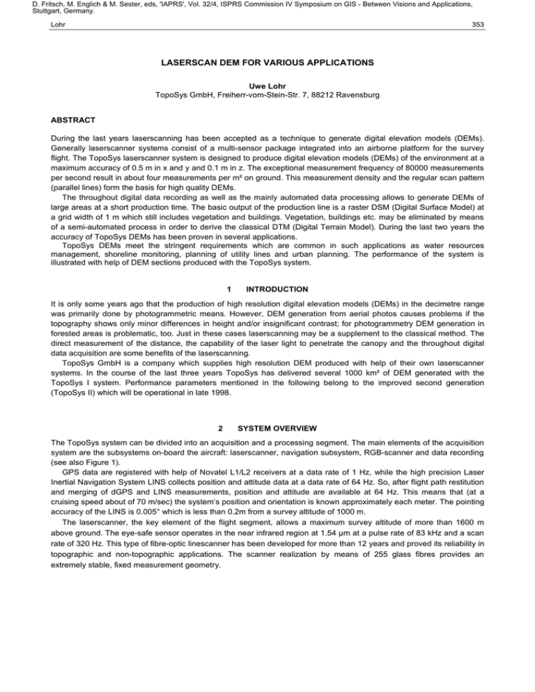
D. Fritsch, M. Englich & M. Sester, eds, 'IAPRS', Vol. 32/4, ISPRS Commission IV Symposium on GIS - Between Visions and Applications, Stuttgart, Germany. Lohr 353 LASERSCAN DEM FOR VARIOUS APPLICATIONS Uwe Lohr TopoSys GmbH, Freiherr-vom-Stein-Str. 7, 88212 Ravensburg ABSTRACT During the last years laserscanning has been accepted as a technique to generate digital elevation models (DEMs). Generally laserscanner systems consist of a multi-sensor package integrated into an airborne platform for the survey flight. The TopoSys laserscanner system is designed to produce digital elevation models (DEMs) of the environment at a maximum accuracy of 0.5 m in x and y and 0.1 m in z. The exceptional measurement frequency of 80000 measurements per second result in about four measurements per m² on ground. This measurement density and the regular scan pattern (parallel lines) form the basis for high quality DEMs. The throughout digital data recording as well as the mainly automated data processing allows to generate DEMs of large areas at a short production time. The basic output of the production line is a raster DSM (Digital Surface Model) at a grid width of 1 m which still includes vegetation and buildings. Vegetation, buildings etc. may be eliminated by means of a semi-automated process in order to derive the classical DTM (Digital Terrain Model). During the last two years the accuracy of TopoSys DEMs has been proven in several applications. TopoSys DEMs meet the stringent requirements which are common in such applications as water resources management, shoreline monitoring, planning of utility lines and urban planning. The performance of the system is illustrated with help of DEM sections produced with the TopoSys system. 1 INTRODUCTION It is only some years ago that the production of high resolution digital elevation models (DEMs) in the decimetre range was primarily done by photogrammetric means. However, DEM generation from aerial photos causes problems if the topography shows only minor differences in height and/or insignificant contrast; for photogrammetry DEM generation in forested areas is problematic, too. Just in these cases laserscanning may be a supplement to the classical method. The direct measurement of the distance, the capability of the laser light to penetrate the canopy and the throughout digital data acquisition are some benefits of the laserscanning. TopoSys GmbH is a company which supplies high resolution DEM produced with help of their own laserscanner systems. In the course of the last three years TopoSys has delivered several 1000 km² of DEM generated with the TopoSys I system. Performance parameters mentioned in the following belong to the improved second generation (TopoSys II) which will be operational in late 1998. 2 SYSTEM OVERVIEW The TopoSys system can be divided into an acquisition and a processing segment. The main elements of the acquisition system are the subsystems on-board the aircraft: laserscanner, navigation subsystem, RGB-scanner and data recording (see also Figure 1). GPS data are registered with help of Novatel L1/L2 receivers at a data rate of 1 Hz, while the high precision Laser Inertial Navigation System LINS collects position and attitude data at a data rate of 64 Hz. So, after flight path restitution and merging of dGPS and LINS measurements, position and attitude are available at 64 Hz. This means that (at a cruising speed about of 70 m/sec) the system’s position and orientation is known approximately each meter. The pointing accuracy of the LINS is 0.005° which is less than 0.2m from a survey altitude of 1000 m. The laserscanner, the key element of the flight segment, allows a maximum survey altitude of more than 1600 m above ground. The eye-safe sensor operates in the near infrared region at 1.54 µm at a pulse rate of 83 kHz and a scan rate of 320 Hz. This type of fibre-optic linescanner has been developed for more than 12 years and proved its reliability in topographic and non-topographic applications. The scanner realization by means of 255 glass fibres provides an extremely stable, fixed measurement geometry. D. Fritsch, M. Englich & M. Sester, eds, 'IAPRS', Vol. 32/4, ISPRS Commission IV Symposium on GIS - Between Visions and Applications, Stuttgart, Germany. 354 IAPRS, Vol. 32, Part 4 "GIS-Between Visions and Applications", Stuttgart, 1998 laser sensor laserscanner optics electronics data recording equipment pre-processing & archiving navigation data PCs and peripherals, time synchron., I/F-software dGPS LINS RGB-line scanner quality control coverage control copying uninteruptable power supply dGPS ground reference station(s) 28 VDC, 20 A flight segment ground segment Figure 1: Components of the TopoSys system The scan angle has been chosen to +/- 10° in order to minimise shading effects at the borders of the scan. The glass fibre arrangement provides a regular scan pattern on ground (see also Figure 2) resulting into a measurement density of 4 measurements per m² (assuming a survey altitude of 1000 m). The RGB-linescanner gives a visible information of the survey area. The scanner has been designed to generate colour images of the survey area at a ground resolution of about 0.4 m. flight direction scan n+10 scan n+5 scan n local grid Figure 2: Measurement pattern on ground During the survey the pilot follows the pre-planned flight lines while laser measurements, LINS-, GPS-, and RGBscanner data are stored directly on removable hard discs. Additionally GPS ground reference data are recorded with help of an own mobile GPS ground station or one of the more and more available stationary GPS ground station. In case of longer survey campaigns data copy and archiving has to be done on site. For this purpose as well as for on on-site GPS quality check and coverage control, individual computer systems have been assembled. D. Fritsch, M. Englich & M. Sester, eds, 'IAPRS', Vol. 32/4, ISPRS Commission IV Symposium on GIS - Between Visions and Applications, Stuttgart, Germany. Lohr 355 The laserscanner allows to record „first pulse“ and „last pulse“ simultaneously. While first pulse registration is the optimum choice when surveying the top of objects (e.g. canopy), last pulse registration should be chosen if the final elevation model shall describe the ground surface. The processing of the gathered data takes places „off-line“ with help of a special DEM processing package. The first step is the reconstruction of the flight path (position and orientation) by means of dGPS and LINS data. After flight path restitution the laser distance measurements are converted into elevation data of single flight strips which are later merged to a consistent DEM of the whole survey area. TopoSys DEM are mainly delivered as raster data in a 1 m raster. Due to the high measurement density about 4 measurements are available to calculate the representative of a 1 m grid cell. The high measurement density allows to perform plausibility checks and/or averaging of measurement data. The resulting DEM is a 16 Bit raster data set, geocoded in local co-ordinates providing a z-accuracy which is better than z @ 0,15 m. 3 EXAMPLES FROM SURVEYS The following DEM sections shall illustrate the performance of the TopoSys laserscanner system and the quality of the resulting DEM. All the figures show 1 m raster DEMs in which the only processing was to convert the laser distance measurement into elevations. The DEMs still include buildings and vegetation, however, both can be eliminated by additional post-processing. Figure 3: Coastline near Scheveningen, Netherlands Figure 3 shows on the left hand side as reference a photograph of the coastline close to Scheveningen. In the DEM on the right hand side the elevations are coded as grey values (dark = low; white = high). The flat beach, the well-known recreation platform as well as buildings can clearly be identified in the 1 m raster DEM. Figure 4 shows a section of the 3D city model of Bonn, Germany. The 1 m raster DEM, in this case overlaid with a scanned aerial photograph, forms an excellent data base for 3D city models used in such applications as simulation of transmitter sites for mobile communication, simulation of floods and diverse virtual reality applications. D. Fritsch, M. Englich & M. Sester, eds, 'IAPRS', Vol. 32/4, ISPRS Commission IV Symposium on GIS - Between Visions and Applications, Stuttgart, Germany. 356 IAPRS, Vol. 32, Part 4 "GIS-Between Visions and Applications", Stuttgart, 1998 Figure 4: 3D presentation of an ancient part of Bonn, Germany 4 SUMMARY As mentioned in the beginning, the benefits of laserscanning are: N Laserscanners perform direct distance measurements which are transformed into elevations N Laserscanner are active systems which generate their own measurement signals. Therefore, laserscanners operate independent from external illumination and surveys may even be performed during the night time N The measurement campaigns are done without any signalisation N Laserscanners may penetrate vegetation which is not too dense N The throughout digital data recording and processing allows to generate DEM of larger areas (> 100 km²) in short delivery times Compared with other measurement technique laserscanning provides a dense measurement grid. TopoSys DEM are mainly delivered in a 1m to 2 m grid. Experience from recent years shows that the system is very effective for DEM generation in N river basins as data base for simulation of floods and planning of engineering work N areas with low differences in elevation and/or minor contrast (like the coastal zone) to monitor erosion processes N forested areas to generate DTMs of the forest ground floor N cities for 3D-city models, flood risk estimations,.....
