THE MAPPING PERFORMANCE OF THE HRSC / SRC IN MARS...
advertisement

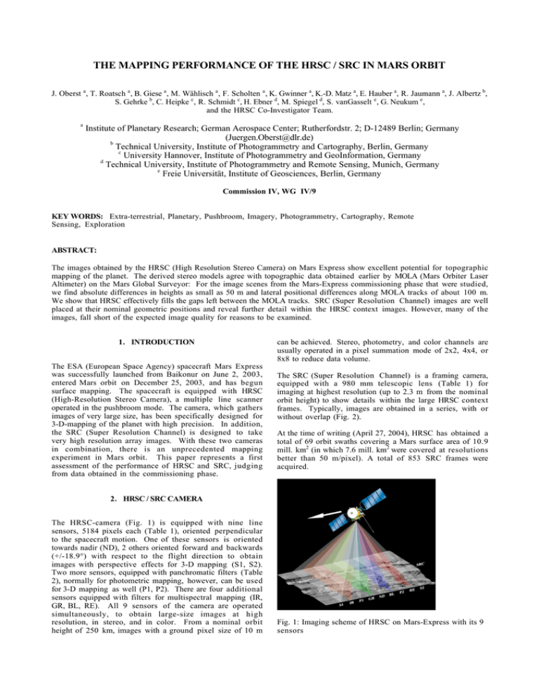
THE MAPPING PERFORMANCE OF THE HRSC / SRC IN MARS ORBIT J. Oberst a , T. Roatsch a , B. Giese a , M. Wählisch a , F. Scholten a , K. Gwinner a, K.-D. Matz a, E. Hauber a, R. Jaumann a, J. Albertz b, S. Gehrke b, C. Heipke c , R. Schmidt c, H. Ebner d, M. Spiegel d, S. vanGasselt e , G. Neukum e , and the HRSC Co-Investigator Team. a Institute of Planetary Research; German Aerospace Center; Rutherfordstr. 2; D-12489 Berlin; Germany (Juergen.Oberst@dlr.de) b Technical University, Institute of Photogrammetry and Cartography, Berlin, Germany c University Hannover, Institute of Photogrammetry and GeoInformation, Germany d Technical University, Institute of Photogrammetry and Remote Sensing, Munich, Germany e Freie Universität, Institute of Geosciences, Berlin, Germany Commission IV, WG IV/9 KEY WORDS: Extra-terrestrial, Planetary, Pushbroom, Imagery, Photogrammetry, Cartography, Remote Sensing, Exploration ABSTRACT: The images obtained by the HRSC (High Resolution Stereo Camera) on Mars Express show excellent potential for topographic mapping of the planet. The derived stereo models agree with topographic data obtained earlier by MOLA (Mars Orbiter Laser Altimeter) on the Mars Global Surveyor: For the image scenes from the Mars-Express commissioning phase that were studied, we find absolute differences in heights as small as 50 m and lateral positional differences along MOLA tracks of about 100 m. We show that HRSC effectively fills the gaps left between the MOLA tracks. SRC (Super Resolution Channel) images are well placed at their nominal geometric positions and reveal further detail within the HRSC context images. However, many of the images, fall short of the expected image quality for reasons to be examined. 1. INTRODUCTION The ESA (European Space Agency) spacecraft Mars Express was successfully launched from Baikonur on June 2, 2003, entered Mars orbit on December 25, 2003, and has begun surface mapping. The spacecraft is equipped with HRSC (High-Resolution Stereo Camera), a multiple line scanner operated in the pushbroom mode. The camera, which gathers images of very large size, has been specifically designed for 3-D-mapping of the planet with high precision. In addition, the SRC (Super Resolution Channel) is designed to take very high resolution array images. With these two cameras in combination, there is an unprecedented mapping experiment in Mars orbit. This paper represents a first assessment of the performance of HRSC and SRC, judging from data obtained in the commissioning phase. can be achieved. Stereo, photometry, and color channels are usually operated in a pixel summation mode of 2x2, 4x4, or 8x8 to reduce data volume. The SRC (Super Resolution Channel) is a framing camera, equipped with a 980 mm telescopic lens (Table 1) for imaging at highest resolution (up to 2.3 m from the nominal orbit height) to show details within the large HRSC context frames. Typically, images are obtained in a series, with or without overlap (Fig. 2). At the time of writing (April 27, 2004), HRSC has obtained a total of 69 orbit swaths covering a Mars surface area of 10.9 mill. km2 (in which 7.6 mill. km2 were covered at resolutions better than 50 m/pixel). A total of 853 SRC frames were acquired. 2. HRSC / SRC CAMERA The HRSC-camera (Fig. 1) is equipped with nine line sensors, 5184 pixels each (Table 1), oriented perpendicular to the spacecraft motion. One of these sensors is oriented towards nadir (ND), 2 others oriented forward and backwards (+/-18.9°) with respect to the flight direction to obtain images with perspective effects for 3-D mapping (S1, S2). Two more sensors, equipped with panchromatic filters (Table 2), normally for photometric mapping, however, can be used for 3-D mapping as well (P1, P2). There are four additional sensors equipped with filters for multispectral mapping (IR, GR, BL, RE). All 9 sensors of the camera are operated simultaneously, to obtain large-size images at high resolution, in stereo, and in color. From a nominal orbit height of 250 km, images with a ground pixel size of 10 m Fig. 1: Imaging scheme of HRSC on Mars-Express with its 9 sensors Table 1: HRSC / SRC parameters ========================================== HRSC SRC Focal Length, mm 175.0 988.6 +) f/ratio f/5.6 f/9.2 IFOV, rad/pixel 0.000040 0.0000092 Field of View (rad) Cross-track 0.2000 0.0094 Along-track 0.6597 ++) 0.0094 Pixel Size, microns 7.0 9.0 Detector Array Size 5184 *) 1024 x 1024 **) ========================================== +) Actual laboratory-calibrated flight model; the nominal value is 975.0 mm. ++) The HRSC along-track FOV size is assumed to be equal to the angular separation between the first and last line detector. It is nominally equal to 2 x 18.9° = 37.8°, where 18.9° is the nominal stereo angle. *) The HRSC sensor lines have 5272 "physical" pixels but only 5184 of them are used for image reconstruction and processing **) The SRC has 1032 pixels and 1024 lines; however, only 1008 lines and 1008 pixels are available after calibration. Table 2: Band width of HRSC filters ======================================== Detector Band Center Bandwidth # [nanometers] S1 675 180 RED 750 40 P2 675 180 BLUE 440 90 NADIR 675 180 GREEN 530 90 P1 675 180 IR 970 90 S1 675 180 ======================================== 3. SYSTEMATIC AND STANDARD PHOTOGRAMMETRIC PROCESSING The data processing essentially follows procedures, as they were described earlier at an ISPRS conference in 1995 (Oberst et al., 1995). Following receipt on the ground, the data are decompressed and radiometrically calibrated resulting in “Level-2” products. Further systematic processing includes geometric corrections. The nominal orbit, pointing, and geometric calibration data are used t o project the images onto a 5 km/pix-MOLA Digital Planetary Radii Model as a reference surface (“Level-3” products). The five panchromatic channels in the Level-2 image data are subjected to image matching for the production of DEMs (Digital Elevation Models). The data are typically smoothed to remove data compression artifacts beforehand. Gaps in the matching are filled by interpolation to warrant smooth terrain models for the further processing. The DEMs are typically produced with a grid resolution of 200 m. Efforts are under way to derive terrain models of higher resolutions (50 m/DEM pixel) in selected areas, surface textures, illumination geometry, and atmospheric conditions permitting. The “effective” resolution of details in the terrain models remains to be studied (see discussion further below). By combination of the Level-2 data and the DEMs, orthoimages are produced. Various additional products include anaglyphs, oblique views, and movies. The processing ultimately results in topographic color image maps (Albertz et al., 2004). Fig. 2: SRC imaging schemes. The images are not to scale: SRC covers only 4% of the nominal HRSC sensor swath 4. INTERNAL CONSISTENCY In order to make the topographic mapping with high accuracy possible, the viewing rays from conjugate points identified in the three stereo sensors (or five, when the panchromatic camera sensors are included), ideally, must intersect. We wish to examine, how well this condition i s met. We first of all collected a large number of such conjugate points using a digital image matcher (Fig. 3). The HWMATCH1 program (developed for the HRSC project, Heipke et al., 2004), which identifies large numbers of “points of interest” and measures their line/sample coordinates, is ideally suited for this task. Normally, > 1000 such points of interest are found within one typical HRSC orbit strip. Using the nominal orbit and pointing data, as delivered from the Mars Express navigation team, we determined the viewing ray vectors and the “intersection point” of the viewing rays, i.e. the point where the three rays have their closest approach. A plane perpendicular to the surface normal was then placed through this intersection point. The actual ray intersection points were plotted with respect t o this plane (Fig. 4). First tests revealed an internal time-tag error of 8 ms, associated with the nadir channel, consistent with communications from the camera manufacturing team. This error was removed to first order for this further study. Inspection of the corrected data suggests that > 99% of the stereo rays intersect within a sphere of radius 20m, which i s an impressive result, considering that the pixel resolution i s only 12.5 m for the nadir sensor and 25 m for the two stereo channels. We conclude that the internal consistency of the HRSC stereo mapping experiment, even with nominal orbit and pointing data, is excellent. Fig. 3: Screen shot showing small sections of the HRSC scene (left: nadir, center: stereo1, right: stereo2) from orbit 18 and conjugate points identified by HWMATCH1. by-shot along tracks, with spacings of approx. 300 m on the ground. While the data coverage is quite dense near the poles (MGS was in a polar orbit), there is a spacing of the MOLA tracks of several kilometers near the equator. Contiguous terrain models are obtained by interpolation. Owing to the considerable laser surface spot size of approx. 160 m, the measurements involve some averaging over a patch. The relative or absolute height accuracy of individual MOLA shots was estimated to be better than 50 cm or 1.5 m, respectively (Smith et al., 2001; Neumann et al., 2003). We derived a HRSC-DEM with an effective resolution of 300 m per grid pixel (Fig. 5), specifically for a comparison with the available MOLA gridded model, which was originally interpolated from MOLA tracks (which typically run in the North/South direction). Note that 300m corresponds to MOLA’s shot-to-shot spacing. Four different profiles were placed across the DEM. The profiles p1-p3 are oriented exactly along MOLA tracks, while p4 is purposely placed across the MOLA tracks. Fig. 4: Ray intersection points with the surface for rays from the nadir (blue), the stereo1 (red), and the stereo 2 (green) channel. 97% of the rays meet within a sphere of radius 20m. 5. COMPARISON WITH MOLA The Mars Orbiter Laser Altimeter (MOLA) on board the Mars Global Surveyor (MGS) has completed its mapping of the planet in June 2001. MOLA data have practically redefined the Mars-coordinate system and established a new reference surface for the planet. Therefore, a comparison of our stereoderived terrain data with MOLA models provides an excellent test for accuracy of the HRSC within the Marsfixed coordinate system. The MOLA data are obtained shot- The stereo and laser altimeter terrain models show excellent agreement. The differences in absolute heights are on the order of 50 m only and horizontal offsets are about 100 m for this orbit. These minor offsets are to be removed b y bundle block adjustment techniques (Ebner et al., 2004). Judging from the profiles p1, p2, and p3, the HRSC terrain model of 300m scale shows details at a level similar to the MOLA model. Further studies are under way to improve the resolutions of the HRSC models for more detail. In MOLA’s across-track direction, our stereo terrain model already exceeds the spatial resolution of the MOLA models (see profile p4), suggesting that HRSC conveniently fills gaps i n the coverage left by MOLA. Fig. 5: Left: Terrain Model derived from HRSC-images (nadir, forward, and backward) acquired during orbit 18. Heights in this model span a range of approx. 3 km and are represented by image brightness. Right: Topographic profiles p1, p2, p3, and p4 extracted from this model and from a corresponding MOLA gridded terrain model. 6. PERFORMANCE OF SRC The SRC camera with its large focal length (Table 1) i s intended to provide high resolution detail within the context of the large HRSC scenes. We selected SRC images from orbit 37 and orbit 68 for analysis (Figs. 6, 7). Both, SRC images and HRSC context images were reprojected to a reference HRSC terrain model. The SRC images were mosaicked using the nominal time tag, orbit, and spacecraft pointing data. The SRC images fit nicely into the predicted location within the HRSC context. Only minor offsets in the across-track direction of < 100 SRC pixels are observed (presumably due to offsets from the nominal co-alignment between the cameras), which require small shifting to make the SRC and HRSC images precisely fit. (However, some few SRC images suffer from large time-tag errors which place the SRC images into completely erroneous locations of the HRSC context.) Using a digital image matcher as a tool for position measurement of features in the images, we made a rough estimate that the magnification factor of SRC with respect t o HRSC is 4.33, corresponding to an effective focal length of 974.5 mm. This value is in good agreement with the nominal focal length (Table 1), but it is 1.5% lower than the value that has been directly measured on the ground. The SRC position (position of the upper left corner of the SRC image) within the HRSC scene is re-estimated to be at pixel # 2694.0. The effective image resolution improvement over HRSC (see Fig. 5b), estimated to be approx. a factor of 2, remains below the expectations judging from the images that have been examined. The quality of the SRC images appears to vary from orbit to orbit or even within orbits, an effect, which is currently being studied. . Fig. 6a: Portion of a HRSC swath (orbit 68, near the caldera of Ascraeus Mons) with image footprints of SRC images shown. The SRC image belonging to the red footprint is shown below. The width of the SRC images is approx. 2 km. Fig. 6b: The SRC image (left, see Fig. 6a for footprint within HRSC context) in comparison with the corresponding (magnified by a factor of 4) portion of the HRSC swath (right). Why the effective improvement in resolution of the SRC over the HRSC image falls behind expectations requires further study. Fig. 7: Left: Small portion of the HRSC swath within the Olympus Mons caldera, obtained during orbit 37. The black rectangle (size: approx. 2 x 4 km) marks the area, where SRC images were obtained. Right: Mosaic of two SRC images. 7. SUMMARY References: Though MarsExpress is still in the commissioning phase and though little time has been available for a first image data analysis, we can draw the following preliminary conclusions: Albertz, J., S. Gehrke, M. Wählisch, H. Lehmann, T. Schumacher, G. Neukum, and the HRSC Co-Investigator team, Digital cartography with HRSC on Mars-Express, this meeting. Relative Accuracy: • Even with nominal navigation data, solid ray intersections (+/-20 m) and reliable terrain models can be derived Ebner, H., M. Spiegel, A. Baumgartner, B. Giese, G. Neukum, and the HRSC Co-investigator team, Improving the exterior orientation of Mars-Express HRSC imagery, this meeting. Absolute Accuracy: • Excellent qualitative agreement between HRSC and MOLA terrain models • Typical offsets in absolute height approx. 50 m (more orbits to be studied!) • Offsets in lateral positioning approx. 100 m, mostly alongtrack (more orbits to be studied!) Heipke, C., R. Schmidt, R. Brand, J. Oberst, G. Neukum, and the HRSC Co-investigator team, Performance of automatic tie point extraction using HRSC imagery of the MarsExpress mission, this meeting. SRC Mapping: • Positioning of most SRC images in good agreement with context HRSC (Level-3) scenes • Mosaicking of SRC-orthoimages is straightforward • Time-tag and positioning errors as well as image quality issues must undergo further studies We expect that the data products from HRSC/SRC will stimulate major advancements in the geology and geophysics of Mars. Neumann, G.A., F.G. Lemoine, D.E. Smith, M.T. Zuber, The Mars Orbiter Laser Altimeter Archive: Final Precision Experiment Data Record Release and Status of Radiometry, Lunar Planetary Science XXXIV, #1978, 2003. Oberst, J., B. Giese, T. Roatsch, K. Eichentopf, W. Tost, A. Harris, R. Reulke, R. Jaumann, and G. Neukum, Mars '94/'96 Pushbroom Cameras: Plans for Ground Data Processing and Analysis, ISPRS Vol. XXX, Part4, 533-540, 1995. Smith et al., Mars Orbiter Laser Altimeter: Experiment summary after the first year of global mapping of Mars, J. Geophys Res., Vol. 106, No. E10, 23,689-23,722, 2001.

