Estimating Sensor Pose from Images of a Stereo Rig
advertisement
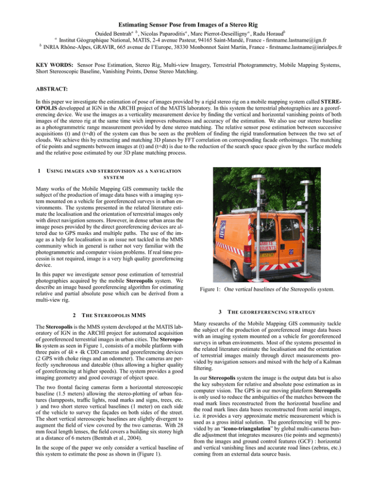
Estimating Sensor Pose from Images of a Stereo Rig Ouided Bentrah , Nicolas Paparoditis , Marc Pierrot-Deseilligny , Radu Horaud Institut Géographique National, MATIS, 2-4 avenue Pasteur, 94165 Saint-Mandé, France - firstname.lastname@ign.fr INRIA Rhône-Alpes, GRAVIR, 665 avenue de l’Europe, 38330 Monbonnot Saint Martin, France - firstname.lastname@inrialpes.fr KEY WORDS: Sensor Pose Estimation, Stereo Rig, Multi-view Imagery, Terrestrial Photogrammetry, Mobile Mapping Systems, Short Stereoscopic Baseline, Vanishing Points, Dense Stereo Matching. ABSTRACT: In this paper we investigate the estimation of pose of images provided by a rigid stereo rig on a mobile mapping system called STEREOPOLIS developped at IGN in the ARCHI project of the MATIS laboratory. In this system the terrestrial photographies are a georeferencing device. We use the images as a verticality measurement device by finding the vertical and horizontal vanishing points of both images of the stereo rig at the same time wich improves robustness and accuracy of the estimation. We also use our stereo baseline as a photogrammetric range measurement provided by dene stereo matching. The relative sensor pose estimation between successive acquisitions (t) and (t+dt) of the system can thus be seen as the problem of finding the rigid transformation between the two set of clouds. We achieve this by extracting and matching 3D planes by FFT correlation on corresponding facade orthoimages. The matching of tie points and segments between images at (t) and (t+dt) is due to the reduction of the search space space given by the surface models and the relative pose estimated by our 3D plane matching process. 1 U SING IMAGES AND STEREOVISION AS A NAVIGATION SYSTEM Many works of the Mobile Mapping GIS community tackle the subject of the production of image data bases with a imaging system mounted on a vehicle for georeferenced surveys in urban environments. The systems presented in the related literature estimate the localisation and the orientation of terrestrial images only with direct navigation sensors. However, in dense urban areas the image poses provided by the direct georeferencing devices are altered due to GPS masks and multiple paths. The use of the image as a help for localisation is an issue not tackled in the MMS community which in general is rather not very familiar with the photogrammetric and computer vision problems. If real time processin is not required, image is a very high quality georeferncing device. In this paper we investigate sensor pose estimation of terrestrial photographies acquired by the mobile Stereopolis system. We describe an image based georeferencing algorithm for estimating relative and partial absolute pose which can be derived from a multi-view rig. 2 T HE S TEREOPOLIS MMS The Stereopolis is the MMS system developed at the MATIS laboratory of IGN in the ARCHI project for automated acquisition of georeferenced terrestrial images in urban cities. The Stereopolis system as seen in Figure 1, consists of a mobile platform with three pairs of k CDD cameras and georeferencing devices (2 GPS with choke rings and an odometer). The cameras are perfectly synchronous and dateable (thus allowing a higher quality of georeferencing at higher speeds). The system provides a good imaging geometry and good coverage of object space. The two frontal facing cameras form a horizontal stereoscopic baseline (1.5 meters) allowing the stereo-plotting of urban features (lampposts, traffic lights, road marks and signs, trees, etc. ) and two short stereo vertical baselines (1 meter) on each side of the vehicle to survey the façades on both sides of the street. The short vertical stereoscopic baselines are slightly divergent to augment the field of view covered by the two cameras. With 28 mm focal length lenses, the field covers a building six storey high at a distance of 6 meters (Bentrah et al., 2004). In the scope of the paper we only consider a vertical baseline of this system to estimate the pose as shown in (Figure 1). Figure 1: One vertical baselines of the Stereopolis system. 3 T HE GEOREFERENCING STRATEGY Many researchs of the Mobile Mapping GIS community tackle the subject of the production of georeferenced image data bases with an imaging system mounted on a vehicle for georeferenced surveys in urban environments. Most of the systems presented in the related literature estimate the localisation and the orientation of terrestrial images mainly through direct measurements provided by navigation sensors and mixed with the help of a Kalman filtering. In our Stereopolis system the image is the output data but is also the key subsystem for relative and absolute pose estimation as in computer vision. The GPS in our moving plateform Stereopolis is only used to reduce the ambiguities of the matches between the road mark lines reconstructed from the horizontal baseline and the road mark lines data bases reconstructed from aerial images, i.e. it provides a very approximate metric measurement which is used as a gross initial solution. The georeferencing will be provided by an “icono-triangulation” by global multi-cameras bundle adjustment that integrates measures (tie points and segments) from the images and ground control features (GCF) : horizontal and vertical vanishing lines and accurate road lines (zebras, etc.) coming from an external data source basis. Of course, in an overall system design, measurements provided by odometers and GPS can help the image processing by reducing the search spaces and as consequence by reducing processing times and robusteness. Figure 4: MMS Images taken by use of the vertical baselines. Figure 2: Georeferencing strategy of terrestrial images using features. 3.1 Measuring relative pose from the image sequences Exterior orientation in photogrammetry and pose estimation as it is mostly called in computer vision is a popular research subject. In this paper, we investigate the use of higher-level geometric features such as 3D points, 3D lines or 3D planes generated from a range measurements unit as observed geometric entities to improve the automation of the sensor pose estimation. The cameras used on our system have fixed focal lengths. They are calibrated on a 3D target polygon and on a planar textured wall. Focal length, principal point of autocollimation, principal point of symmetry and the coefficients of a radial distorsion polynom are estimated. The image residues are generally of a tenth of a pixel. The relative pose between the different cameras composing the rig are also determined on the 3D target polygon. through the sampled gradient measurement in the gradient direction. This improvement in localisation reduces in a significant way the aliasing affects thus the shapes are much smoothly described and as a consequence determining ”intelligent” thresholds for polygonal approximation is much easier. The estimation uses an iterative merging process based on the maximum residual using the orthogonal regression (Taillandier and Deriche, 2002). One of the advantages of using orthogonal regression is that the errors associated with the straight lines parameters can be determined. First, the polylines whose merging gives a minimal maximum residual are merged. The tolerance on the polygonal approximation acts us to stop the process when the merging has a maximum residual above a threshold given by the user. Once the polygonal approximation is done, the parameters and of the lines underlying the segments as well as the variance covariance matrix of these parameters are estimated by using the results of (Deriche et al., 1992) algorithm and under the assumption that the edges detected by the Canny-Deriche detector have a variance given by : ¾ ¾ where can be determined through the ratio signal/noise in the images (see Figure 5). As the cameras are perfectly synchronised and since the relative orientation of the cameras on the vehicle are known, all the cameras and their very different viewing geometry will contribute to determine robustly and accurately the vertical and horizontal vanishing points and as a consequence to estimate the roll and pitch angles of the platform (with respect to the vehicle displacement). Figure 5: Sub pixel lines segments for two images. Figure 3: Estimating the roll and the pitch angles of the platform. 3.2 Sub-Pixel Features Detection The first step of the straight lines detection stage is the computation of image derivatives followed by the non-maximum suppression using the optimal Canny-Deriche edge detector (Deriche, 1987). The contour pixels are thereafter chained and are subpixellocalised by finding the maxima of an analytical function fitted Figure 6: Illustration of detected line segments. 3.3 Vanishing Points Detection Due to the effects of perspective projection, the line segments parallel in the 3D world intersect themselves in image space. Depending on the orientation of the lines the intersection point can be finite or infinite and is referred to as vanishing point. There are many methods for vanishing points detection in the images. A good review is given by V. Heuvel, (Van den Heuvel, 1998). Here the vanishing points detection is based on an extension of the method proposed by Shufelt (Shufelt, 1999) generalised to multi-head viewing (Figure 7). As seen in (Figure 7 - a) the image segments of each relatively calibrated view (to an image segment corresponds a 3D plane intersecting the sphere) are accumulated on the same plane tangent to the north pole (considering that the horizontally oriented cameras are on the equator). The most dominant groups of converging lines segments in the image will produce maxima on the accumulator. To avoid aliasing problems, each segment ( and on Figure 7 - b) accumulates between its uncertainty bounding segments with an ad-hoc weighting function to take into account the uncertainty on the contour and the segment extractions, the approch is based on edge error modeling to guide the search for vanishing points. This fuzzy accumulation thus indirectly takes into account that long segments should weigh more than small ones. The width of the the segments band indicates the degree of uncertainty in the orientation of an edge. can be classified and associated to a plane direction. These plane directions will be used, as shown further, to infirm the 3D planes extracted from the DSM generated from the vertical baseline Figure 9: The detected horizontal vanishing points of MMS image pair corresponding to the local maxima of an accumulation on a cylinder tangent at the equator. Figure 10: The line segments associated to princicipal orientations in the scene. 3.4 Digital Façade Models We have now estimated for each rigid capture the pitch and the roll of the moving platform. Let us now estimate the relative yaw and pose of captures at time and with the help of the short vertical base line. (a) (b) (c) Figure 7: (a) Planar method of vanishing points detection using the Gaussian sphere. (b) Bounds for line segments in image space. (c) Bounds for line segments for a fuzzy accumulation on the tangent plane at the pole of the Gaussian sphere. Figure .8 shows the accumulator where only two images of one vertical baseline have accumulated. Of course, for obvious geometric reasons, the highest gain in precision will occurs when mixing images from the vertical and the horizontal baselines when the full system will be operationel. Our short stereo vertical baselines acts as a very precise range measurement unit. In our case even with a short baseline favouring image matching, one meter baseline provides a relative depth accuracy of 5 millimetres on a façade at a distance of 10 meters (with a disparity estimation accuracy of 0.25 pixels). A dense raster-based Digital Façade Surface Model (DFM) is processed by a dynamic programming optimisation method matching globally conjugate epipolar lines (Baillard, 1997) integrating edges with subpixel accuracy and adapted to landscapes with discontinuities. Figure 11: Dense Digital Façade Model computed from the short vertical stereo baseline at (t) and (t+dt). (a) (b) (c) 3.5 Figure 8: (a) & (b) The detected vertical vanishing points for each MMS image of the vertical baseline independently. (c) Multi-view vertical vanishing point accumulation. Once the vertical vanishing point has been found we accumulate the non vertical segments on a cylinder tangent at the corresponding equator (considering the oriented horizontal cameras at the equator) to find all horizontal vanishing points (Figure 9). The accumulator cells do not need to have a high angular resolution. Each vanishing point corresponds to a different 3D plane orientation relatively to the image planes. Thus horizontal segments Extracting 3D Planes 3D planes and the set of 3D points belonging to these planes are extracted in the 3D dense DFM with a robust region growing algorithm mixed with a robust estimator RANSAC of Fischler and Bolles (Fischler and Bolles, 1981). The aim is a robust detection of the dominant façade planes. We randomly select a triple of points and evaluate the resulting hypothesis of planes, we perform a RANSAC based plane detection algorithm in a local neighborhood. This means that, assuming that we have a sufficient overlap between two acquisition of the rig, the rotation between two poses can be estimated by finding the matching planes subsets. Figure 12: Two view of the extracted 3D planes from digital façade model by robust region growing algorithm mixed with a RANSAC . 3.6 Estimating relative orientations by façade orthoimage correlation Translation Formulation This phase investigate matching 3D planes by a FFT correlation. The matching planes can be found by façade orthoimage correlation. Let us consider two possible matching planes. If both orthoimages are constructed, i.e. images are resampled from perspective view to orthogonal projection on the considered plane, they are superposable modulo a translation. This orthoimage translation is extremely interesting because it provides directly the translation of the plateform in the plane. In our case, we estimate the translation by a FFT matching on the façade adaptive shape template. One of the major advantages of this method is that it still works when the MMS turns round corners without having a video acquisition rate. Let us consider two orthoimages ½ , ¾ respectively at time and and two adaptative masks for a pair of homologous planes ½ , ¾ . If two orthoimages ½ , ¾ differ by shift , i.e., ¾ ½ , then Fourier Transforms formulas can be expressed by : ¼ ¾ ¾¾ ½ ¾ ¾ ½ ¾ ¾¾ ½ ¾ ½ ½½ ½ ½½ ½¾ ½ ¼ ½½ ½ ½ ¼ ½ ½ ¾ (1) ½¾ ½ ¾ (2) ½ ¾ ½ ¾ (3) ¾ ¼ (4) ¾ ½¾ ½¾ ½ ¾ ¼ ½¾ ½½ ½¾ Figure 14: Correlation surface between two orthoimages by FFT correlation techniques. Rotation Formulation and Method This section formulates the 3D rotation matrix problem between the image pairs. Let consider two possible homologous planes ´µ and ´·µ . and here are the two normals vectors of the ´µ (5) The Cross Correlation Score is processed by : Figure 13: Orthoimages and Corresponding Masks for a pair of homologous planes at and . (6) By taking an inverse Fourier Transform of , we can find the position with the maximum absolute value. The relative distance to the façade between cameras can be recovered in this case as there we have a verticale basis. It corresponds to displacement . ´·µ matching planes in the image reference system. Let us first denote a rotation value around axis with an angle by . Let us call ´µ ½ the rotation passing from the internal image reference system to the local tangent ground system (rotation of pitch and roll angles relatively to the vehicle motion with the help of the short vertical base line and vanishing points). Let us denote ´µ½ the rotation passing from the ground system of frames at to the reference system of the 3D planes ½ . and finally, let us consider ´µ ½ ¾ the rotation matrix passing from the camera 1 to camera 2. ´µ and ´·µ can be calculated by : ´µ the rotation matrix by : We can compute ½ ½ ¾ ¾ (7) where ½ and ¾ are respectively the cameras projective centres. (8) ´µ ´·µ ´µ ´·µ ´µ ´·µ ´µ ´·µ (9) So we get the desired values of rotations by computing : ´µ´·µ ´·µ ½ ½ ´µ½ (10) As a result, we get the desired values of relative shift and rotations that are the desired parameters of approximate solution to initialise our photogrammetric bundle. 4 E STIMATING ROBUST AND ACCURATE TIE POINTS AND SEGMENTS We have up to now estimated the approximate relative orientation of the platform and DFMs expressed in the platform system for each capture. This approximate relative orientation is necessary to initialise the bundle adjustment in order to linearise the bundle system. Moreover both depth and pose information provide a very good predictor to restrict image-matching search space an consequently find very robust matches by image correlation that can be directly inserted as accurate tie point and segments measurements in the photogrammetric bundle of stereo pairs to provide high-precision orientation parameters of the images : rotation matrix giving the angular orientation of the second couple in the first, and three translational displacements giving the direction of the inter-couple translation. The 3D relative position and orientation of images in object space will be determined by a Global Multi-Cameras Bundle Adjustment “icono-triangulation” that integrates measures from the images (intra-stereo tie points and segments), measures from GPS with their uncertainties, ground control features : horizontal and vertical vanishing lines and accurate road marks. The mathematical model applied for sequential MMS images orientation is based on least-squares adjustment (Jung and Boldo, 2004). 5 C ONCLUSION We have presented an original way of estimating pose from images of a stereo rig in the case of planar scenes as encountered in urban areas. Stereo rigs provide a metric and a scale in the pose estimation problem. They also hugely decrease the robustness of tie point estimation which is in general the weakness of target tracking algorithms in image sequences. The 2D ill-posed matching is transformed in a well 3D matching problem. We do not need to have short baseline in the motion, our system is wide baseline efficient thus we do not need to have such important frame rates as in video sequences. Stereo rigs with short baselines also provide very good surface models to initialize a fine multiview surface reconstruction scheme after a bundle adjustement of all images acquired by the system has been performed. REFERENCES Baillard, C., 1997. Analyse d’images aériennes stéréo pour la restitution 3D en milieu urbain. PhD thesis, ENST, Laboratoire MATIS. Bentrah, O., Paparoditis, N. and Pierrot-Deseilligny, M., 2004. Stereopolis: An image based urban environments modeling system. In: MMT 2004. The 4th International Symposium on Mobile Mapping Technology, Kunming, China. Deriche, R., 1987. Using canny’s criteria to derive a recursively implemented optimal edge detector. In: International Journal of Computer Vision, Vol. 1number 2, pp. 167–187. Deriche, R., Vaillant, R. and Faugeras, O., 1992. In theory and applications of image analysis, chapter from noisy edges points to 3D reconstruction of a scene : A robust approach and its uncertainty analysis. In: World Scientific. Series in Machine Perception and Artificial Intelligence, pp. 71–79. Fischler, M. A. and Bolles, R. C., 1981. Random sample consensus: A paradigm for model fitting with applications to image analysis and automated cartography. In: Comm. Assoc. Comp. Mach, Vol. 24number 6, pp. 381–395. Jung, F. and Boldo, D., 2004. Bundle adjustment and incidence of linear features on the accuracy of external calibration parameters. In: Proc. ISPRS, Istambul, 2004, to appear. Shufelt, J. A., 1999. Performance evaluation and analysis of vanishing point detection techniques. In: IEEE Transactions On Pattern Analysis and Machine Intelligence, Vol. 21number 3, pp. 282–288. Taillandier, F. and Deriche, R., 2002. Reconstruction of 3D linear primitives from multiple views for urban areas modelisation. In: Proceedings PCV02, Vol. B. Van den Heuvel, F. A., 1998. Vanishing point detection for architectural photogrammetry. In: H. Chikatsu and E. S. Editors (eds), International Archives of Photogrammetry and Remote Sensing, Vol. 32number 5, pp. 652–659.
