Document 11731641
advertisement
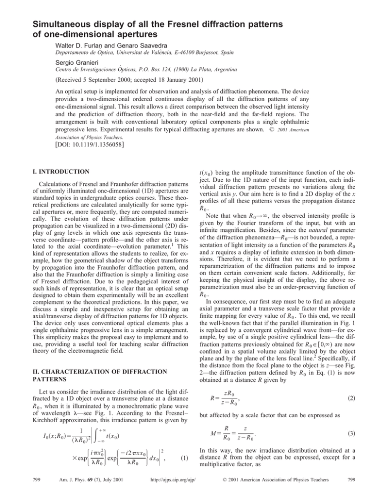
Simultaneous display of all the Fresnel diffraction patterns of one-dimensional apertures Walter D. Furlan and Genaro Saavedra Departamento de Óptica, Universitat de València, E-46100 Burjassot, Spain Sergio Granieri Centro de Investigaciones Ópticas, P.O. Box 124, (1900) La Plata, Argentina 共Received 5 September 2000; accepted 18 January 2001兲 An optical setup is implemented for observation and analysis of diffraction phenomena. The device provides a two-dimensional ordered continuous display of all the diffraction patterns of any one-dimensional signal. This result allows a direct comparison between the observed light intensity and the prediction of diffraction theory, both in the near-field and the far-field regions. The arrangement is built with conventional laboratory optical components plus a single ophthalmic progressive lens. Experimental results for typical diffracting apertures are shown. © 2001 American Association of Physics Teachers. 关DOI: 10.1119/1.1356058兴 I. INTRODUCTION Calculations of Fresnel and Fraunhofer diffraction patterns of uniformly illuminated one-dimensional 共1D兲 apertures are standard topics in undergraduate optics courses. These theoretical predictions are calculated analytically for some typical apertures or, more frequently, they are computed numerically. The evolution of these diffraction patterns under propagation can be visualized in a two-dimensional 共2D兲 display of gray levels in which one axis represents the transverse coordinate—pattern profile—and the other axis is related to the axial coordinate—evolution parameter.1 This kind of representation allows the students to realize, for example, how the geometrical shadow of the object transforms by propagation into the Fraunhofer diffraction pattern, and also that the Fraunhofer diffraction is simply a limiting case of Fresnel diffraction. Due to the pedagogical interest of such kinds of representation, it is clear that an optical setup designed to obtain them experimentally will be an excellent complement to the theoretical predictions. In this paper, we discuss a simple and inexpensive setup for obtaining an axial/transverse display of diffraction patterns for 1D objects. The device only uses conventional optical elements plus a single ophthalmic progressive lens in a simple arrangement. This simplicity makes the proposal easy to implement and to use, providing a useful tool for teaching scalar diffraction theory of the electromagnetic field. II. CHARACTERIZATION OF DIFFRACTION PATTERNS Let us consider the irradiance distribution of the light diffracted by a 1D object over a transverse plane at a distance R 0 , when it is illuminated by a monochromatic plane wave of wavelength —see Fig. 1. According to the Fresnel– Kirchhoff approximation, this irradiance pattern is given by I 0 共 x;R 0 兲 ⫽ 冏冕 1 共 R 0 兲 2 ⫻exp 799 ⫹⬁ ⫺⬁ i x 20 R 0 exp R⫽ zR 0 , z⫺R 0 冎 冏 2 ⫺i2 xx 0 dx 0 , R 0 Am. J. Phys. 69 共7兲, July 2001 共1兲 http://ojps.aip.org/ajp/ 共2兲 but affected by a scale factor that can be expressed as M⫽ t共 x0兲 再 冎 再 t(x 0 ) being the amplitude transmittance function of the object. Due to the 1D nature of the input function, each individual diffraction pattern presents no variations along the vertical axis y. Our aim here is to find a 2D display of the x profiles of all these patterns versus the propagation distance R0 . Note that when R 0 →⬁, the observed intensity profile is given by the Fourier transform of the input, but with an infinite magnification. Besides, since the natural parameter of the diffraction phenomena—R 0 —is not bounded, a representation of light intensity as a function of the parameters R 0 and x requires a display of infinite extension in both dimensions. Therefore, it is evident that we need to perform a reparametrization of the diffraction patterns and to impose on them certain convenient scale factors. Additionally, for keeping the physical insight of the display, the above reparametrization must also be an order-preserving function of R0 . In consequence, our first step must be to find an adequate axial parameter and a transverse scale factor that provide a finite mapping for every value of R 0 . To this end, we recall the well-known fact that if the parallel illumination in Fig. 1 is replaced by a convergent cylindrical wave front—for example, by use of a single positive cylindrical lens—the diffraction patterns previously obtained for R 0 苸 关 0,⬁) are now confined in a spatial volume axially limited by the object plane and by the plane of the lens focal line.2 Specifically, if the distance from the focal plane to the object is z—see Fig. 2—the diffraction pattern defined by R 0 in Eq. 共1兲 is now obtained at a distance R given by z R ⫽ . R 0 z⫺R 0 共3兲 In this way, the new irradiance distribution obtained at a distance R from the object can be expressed, except for a multiplicative factor, as © 2001 American Association of Physics Teachers 799 Fig. 1. Optical diffraction by a 1D object under plane-wave illumination. The distance from the object, R 0 , is a parameter that completely characterizes a single diffraction pattern. I 共 x;R,z 兲 ⫽I 0 冉 冊 x R ; . M M 共4兲 Note that now when R 0 →⬁, the scale factor M tends to zero, providing a suitable compensation for the increasing size of the far-field diffraction patterns. On the other hand, for large values of R 0 the distance R is bounded by the value R ⫽⫺z. Therefore, the use of convergent illumination allows every diffraction pattern to be physically obtainable simply by shifting continuously a screen along the optical axis between the object and the cylindrical lens focus. However, we are looking for a 2D single display in which the profiles of these patterns are laid out side by side in an ordered fashion. The achievement of this result is analyzed in the next section. III. SIMULTANEOUS 2D DISPLAY OF 1D DIFFRACTION PATTERNS As stated in Sec. II, all the diffraction patterns of the input object are obtained, with convergent illumination, as transverse irradiance distributions located between the object plane and the focal plane of the illuminating wave. Provided that these patterns present no variations along the vertical axis y, to achieve our goal we need a technique to select Fig. 2. Diffraction patterns of a 1D object generated by a convergent cylindrical wave front. The pattern represented in Fig. 1 is now obtained at a distance R from the input. In this case, two parameters are needed to characterize a single pattern, namely, R and z. horizontal infinitesimal strips of these distributions and to juxtapose them in a single transverse output plane. The optical arrangement that we propose is sketched in Fig. 3. As can be seen in this picture, we can define 1D horizontal strips of infinitesimal width on every transverse plane—each one at a different height y(R 0 )—to be used as axially distributed diffraction channels. The lens L accesses each channel independently, in order to image all of them at the same output plane simultaneously. Due to the axial dispersion of these diffraction channels, to obtain the desired display the optical power of this lens——should be different for each of them, thus varying continuously with the vertical coordinate y, as is deduced as follows. Let us select the diffraction channel characterized by the natural parameter R 0 and an associated height y(R 0 ). This channel is located at a distance R from the object plane according to Eq. 共2兲. It is straightforward from the Gaussian lens equation that, if we fix the distance a ⬘ from L to the output plane, the required optical power for this channel is given by Fig. 3. Setup for the simultaneous visualization of all the Fresnel diffraction patterns of 1D apertures. The varifocal 共progressive兲 lens images an infinitesimal strip of every individual pattern between the input and the focal line in a single output plane. 800 Am. J. Phys., Vol. 69, No. 7, July 2001 Furlan, Saavedra, and Granieri 800 Fig. 4. Normalized transverse location, y/h, and normalized lateral magnification, M 0 /m 0 , in the output plane of the setup in Fig. 3 for different values of R 0 . 共 y 共 R 0 兲兲 ⫽ l⫺R⫹a ⬘ , 共 l⫺R 兲 a ⬘ 共5兲 l being the distance from the input plane to L. In Eq. 共5兲, the dependence on R 0 is implicit through Eq. 共2兲. Note that the choice of the function y(R 0 ) fixes the dependence of the required optical power of L on the vertical coordinate y. An arbitrary selection of it can lead to a function (y) hard to achieve in practice. However, the functional form of y(R 0 ) can be chosen to match (y) with the variation of the optical power of an ophthalmic progressive—also known as varifocal—lens. In this class of lenses there is a continuous almost-linear transition between two optical powers 0 and h corresponding to the so-called near portion and distance portion, respectively.3 In mathematical terms, such a lens presents a variable optical power that can be expressed as 共 y 兲⫽ 共 h⫺ 0 兲 y⫹ 0 , h Fig. 5. Experimental results for two double slits: 共a兲 Slits of 0.18 mm width separated by 1.3 mm and 共b兲 slits of 0.3 mm width separated by 0.65 mm. where ␣ is defined in terms of the system parameters as ␣ ⫽( h ⫺ 0 )l 2 . It is straightforward to show that the function y(R 0 ) selected in this way is a monotonic 共increasing兲 function of R 0 . Therefore, the final reparametrization of the diffraction patterns in terms of the y coordinate in our final display provides a convenient order-preserving mapping of the diffracted field of the object. 共6兲 where h is the extent of the so-called progression zone. This choice of the varifocal lens, besides being inexpensive— progressive ophthalmic lenses cost no more than a medium quality laboratory lens—provides an output in which the diffraction channels are ordered from the near field to the far field if we choose the proper boundary conditions. These constraints are obtained by requiring that for y⫽0 the output displays the image of the channel corresponding to R 0 ⫽R ⫽0—image of the object t(x 0 )—while for y⫽h the output provides the image of the channel corresponding to R 0 →⬁, i.e., R⫽⫺z. In this way, any other particular diffraction channel is obtained, as can be deduced from Eqs. 共2兲, 共5兲 and 共6兲, in the horizontal strip of the output plane located at the coordinate y(R 0 ) satisfying y共R0兲 R0 /␣ , ⫽ h 1⫹R 0 / ␣ 801 Am. J. Phys., Vol. 69, No. 7, July 2001 共7兲 Fig. 6. Cross section of Fig. 5共b兲 showing the intensity profile near the Fraunhofer region. For comparison purposes, the theoretical sinc envelope of the Young fringes is also shown by the dotted line. Furlan, Saavedra, and Granieri 801 Fig. 7. Experimental result for a Ronchi grating of 3.25 lines/mm. On the other hand, it is relevant to obtain the scale factor M 0 (R 0 ) that affects the final image of each diffraction channel with respect to the x profile of the original diffraction pattern described in Eq. 共1兲. This scale factor is obtained by the product of the magnification resulting from the use of convergent illumination—M in Eq. 共3兲—and the lateral magnification provided by the varifocal lens, this latter given by M L共 R 0 兲 ⫽ ⫺a ⬘ , l⫺R 共8兲 where, again, the dependence on R 0 is implicit through Eq. 共2兲. Making explicit this variation, we obtain finally M 0 共 R 0 兲 ⫽m 0 共 1⫹R 0 / ␣ 兲 , 共9兲 where m 0 is the magnification of the image of the object plane. The functional forms of Eqs. 共7兲 and 共9兲 are represented in Fig. 4. As can be seen for values of R 0 corresponding to the near-field diffraction patterns, the variation of the normalized coordinate y(R 0 )/h with R 0 is fast enough to provide a fine sampling of the diffracted field precisely near the object, where the diffraction patterns change faster. On the other hand, for values of R 0 corresponding to the far field, the variation of y(R 0 )/h is slower and the sampling is coarse, according to the fact that in the far field the patterns change slowly with R 0 . The opposite occurs with the normalized magnification: it is unity for the image of the object—R 0 ⫽0—and rapidly decreases where the transverse dimensions of the diffraction pattern become large. In the next section, we present some typical experimental results that show the performances of the proposed optical setup. IV. EXPERIMENTAL RESULTS The system in Fig. 3 was assembled with an ophthalmic progressive lens characterized by 0 ⫽2.75 D and h 802 Am. J. Phys., Vol. 69, No. 7, July 2001 ⫽5.75 D. We used the following values for the distances: z ⫽426 mm, l⫽646 mm, and a ⬘ ⫽831 mm. Figure 5 illustrates the experimental results registered by a chargecoupled-device camera using two double slits of different widths and different separations as input objects. With these inputs we obtained a nice representation of the evolution by propagation of the interference phenomena. It can be seen that the Fraunhofer region of the diffracted field clearly shows the characteristic Young fringes modulated by a sinc function. In order to compare the theoretical and experimental results, a cross section of Fig. 5共b兲 for values of y/h close to 1 is represented in Fig. 6. Another classical example in diffraction theory is the study of diffraction by periodic objects. The self-imaging phenomena—such as the Talbot effect—are interesting and stimulating effects that usually attract the attention of the students. In Fig. 7 we present the experimental result obtained with a Ronchi grating of 3.25 lines/mm, in which several self-imaging planes can be identified. It can be clearly seen that, due to the finite extent of the grating at the input, the number of Talbot images is limited by the socalled walk-off effect.4 V. CONCLUSIONS We proposed a simple experimental setup to obtain a simultaneous display of the whole set of diffraction patterns of 1D apertures. The design was based on the fact that the use of a converging wave front for illuminating the input transparency provides all its diffraction patterns continuously distributed along a finite segment of the optical axis. The 1D nature of these patterns allowed us to consider infinitesimal strips of them as axially dispersed diffraction channels and to use a varifocal lens as a selective imaging element to juxtapose them in a single 2D display. The proposed optical implementation used simply a commercially available ophthalmic progressive lens, resulting in an inexpensive experimental setup. Some examples of classical diffraction patterns show the didactic potential of our proposal. ACKNOWLEDGMENTS This work was supported by Project No. GV99-100-1-01 of the Conselleria de Cultura, Educació i Ciència, Generalitat Valenciana, Spain. The ophthalmic progressive lens used in the experiments was kindly provided by INDO, S.A. 1 See, for example, Fig. 7 in A. Dubra and J. A. Ferrari, ‘‘Diffracted field by an arbitrary aperture,’’ Am. J. Phys. 61, 87–92 共1999兲. 2 J. D. Gaskill, Linear Systems, Fourier Transforms, and Optics 共Wiley, New York, 1978兲, Chap. 10. 3 M. Jalie, The Principles of Ophthalmic Lenses, 4th ed. 共The Association of Dispensing Opticians, London, U.K., 1984兲, Chap. 13. 4 A. W. Lohmann, Optical Information Processing, 3rd ed. (OPTIK⫹INFO, Uttenreuth, 1986兲, Vol. I, Chap. 18. Furlan, Saavedra, and Granieri 802
