Experiment 3: Interference and Diffraction
advertisement
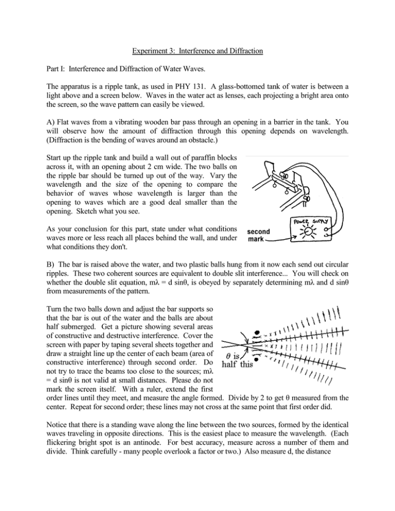
Experiment 3: Interference and Diffraction Part I: Interference and Diffraction of Water Waves. The apparatus is a ripple tank, as used in PHY 131. A glass-bottomed tank of water is between a light above and a screen below. Waves in the water act as lenses, each projecting a bright area onto the screen, so the wave pattern can easily be viewed. A) Flat waves from a vibrating wooden bar pass through an opening in a barrier in the tank. You will observe how the amount of diffraction through this opening depends on wavelength. (Diffraction is the bending of waves around an obstacle.) Start up the ripple tank and build a wall out of paraffin blocks across it, with an opening about 2 cm wide. The two balls on the ripple bar should be turned up out of the way. Vary the wavelength and the size of the opening to compare the behavior of waves whose wavelength is larger than the opening to waves which are a good deal smaller than the opening. Sketch what you see. As your conclusion for this part, state under what conditions waves more or less reach all places behind the wall, and under what conditions they don't. B) The bar is raised above the water, and two plastic balls hung from it now each send out circular ripples. These two coherent sources are equivalent to double slit interference... You will check on whether the double slit equation, mλ = d sinθ, is obeyed by separately determining mλ and d sinθ from measurements of the pattern. Turn the two balls down and adjust the bar supports so that the bar is out of the water and the balls are about half submerged. Get a picture showing several areas of constructive and destructive interference. Cover the screen with paper by taping several sheets together and draw a straight line up the center of each beam (area of constructive interference) through second order. Do not try to trace the beams too close to the sources; mλ = d sinθ is not valid at small distances. Please do not mark the screen itself. With a ruler, extend the first order lines until they meet, and measure the angle formed. Divide by 2 to get θ measured from the center. Repeat for second order; these lines may not cross at the same point that first order did. Notice that there is a standing wave along the line between the two sources, formed by the identical waves traveling in opposite directions. This is the easiest place to measure the wavelength. (Each flickering bright spot is an antinode. For best accuracy, measure across a number of them and divide. Think carefully - many people overlook a factor or two.) Also measure d, the distance - 2 between the two sources. Measured d on the screen, not at the balls themselves, to be consistent with your other measurements. Separately calculate mλ and d sinθ for the first two orders. For your conclusion, say whether the equation mλ = d sinθ seems to be correct. (Assume 10% uncertainty in both mλ and d sinθ.) Part II: Diffraction grating. Caution: Looking directly into the laser beam is dangerous like looking at the sun. Keep the beam and its reflections down at table-top level and keep your eyes above this level. You will check whether light passing through a grating obeys the grating equation. (You have a round piece of clear plastic with thousands of evenly spaced scratches on it, too small to see. The way light scatters from these scratches is equivalent to having many parallel slits. As we will see in section 4, multiple slits produce interference maxima at the same angles that two slits do; they are just narrower maxima. So, the grating equation is the same as the equation for the maxima of a double slit pattern.) Mount the grating in the beam from the laser, it and locate the first order maxima on the wall beyond. They're at a fairly large angle. If you have trouble finding them, place a sheet of paper a few inches from the grating, where you can find them easily, then follow them out. Ignore any spots only a degree or two from the central maximum. These are due to periodic spacing errors on the grating. Measure the distance from the central maximum to the first order on each side, and average. (They may not be the same if the grating and screen are not parallel. Averaging corrects for this.) Note that the end of the tape measure is as shown. Find θ from the geometry of the situation. (Not from mλ = d sinθ. mλ = d sinθ is what you're trying to verify - using it as part of its own proof is circular reasoning.) Find d from the fact that there are 5300 lines per centimeter. Then, calculate the quantity d sinθ (assume it is 3% uncertain). In your conclusion, compare this to mλ. The wavelength of a helium-neon laser is 632.8 nm. Part III. Thin film interference. You will use interference of light to measure the thickness of a piece of plastic, and compare the result to what you get with a micrometer. The thin film in this case is made of air, sandwiched between a pair of glass plates. Rubber bands clamp the plates in contact at one end, while a thin piece of plastic holds their other ends apart, making the air - 3 space wedge shaped. This is viewed with monochromatic light from a mercury lamp, which is reflected from both the top and bottom of the air gap. Where the plates touch, the path difference between these rays is zero, and they interfere destructively there. (One of them undergoes a phase reversal on reflection.) A little over from there, where the gap is λ/4, the path difference is λ/2, giving constructive interference. Where the gap is λ/2, it’s back to destructive interference, and so on. Along the glass, you will see alternating bands of bright and dark, one dark band to the next being an increase of λ/2 in the gap. Thus, counting how many dark bands there are from the contact point to the edge of the plastic tells you the thickness of the plastic in terms of the light’s wavelength. Please do not take the apparatus apart, as the glass will then probably have to be cleaned before the experiment will work again. Observe interference fringes by looking at the reflection of the mercury lamp. With its green filter, this lamp radiates light with a single wavelength, 546 nm. Count (as accurately as you can) the dark interference fringes along the length of the air wedge. Moving some sharp pointer, such as a pencil, along the glass will help you keep track of where you are as you count. You will have to move the lamp to see them. Use this number to compute the thickness of the plastic. Use a micrometer to measure its thickness directly. Enough plastic hangs out the side for you to do this without taking things apart. First, check how the micrometer is zeroed. You will probably find that it's off by at least a fraction of a division. Then, when you read the thickness of the plastic, correct your reading accordingly. Estimate an uncertainty for both values of the thickness. In your conclusion, 1. State whether they agree with each other, and also 2. Comment on which method is the most accurate and why. All together, this lab asks for five conclusions: One each for parts IA, IB, II, and the two questions just above for III. - 4 Phy 133 Experiment 3: Interference and Diffraction Part I: A) Finish Pictures: B) Two Source Interference: λ = __________________ First Order: d = __________________ Second Order: = __________________ = __________________ mλ = __________________ m λ = __________________ d sin = __________________ d sin = __________________ Part II: A) y = _________________ Calculate θ: dist. to screen = ________________ - 5 d sinθ = ______________ mλ = __________________ Part III: Number of fringes = Compute thickness: Measured thickness =
