Concurrency in UML The Concept of Concurrency
Concurrency in UML
Filip Stachecki (NobleProg Poland)
April 8, 2014 - OCUP 2 Program Library, Version 2.6
The Concept of Concurrency
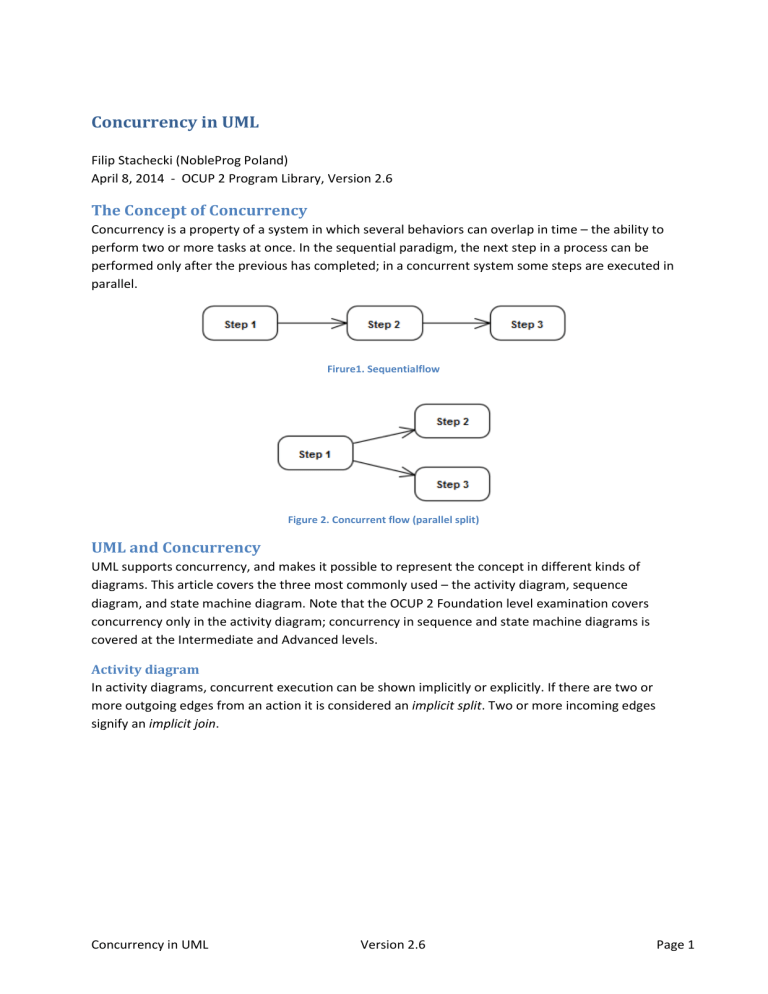
Concurrency is a property of a system in which several behaviors can overlap in time – the ability to perform two or more tasks at once. In the sequential paradigm, the next step in a process can be performed only after the previous has completed; in a concurrent system some steps are executed in parallel.
Firure1. Sequentialflow
Figure 2. Concurrent flow (parallel split)
UML and Concurrency
UML supports concurrency, and makes it possible to represent the concept in different kinds of diagrams. This article covers the three most commonly used – the activity diagram, sequence diagram, and state machine diagram. Note that the OCUP 2 Foundation level examination covers concurrency only in the activity diagram; concurrency in sequence and state machine diagrams is covered at the Intermediate and Advanced levels.
Activity diagram
In activity diagrams, concurrent execution can be shown implicitly or explicitly. If there are two or more outgoing edges from an action it is considered an implicit split . Two or more incoming edges signify an implicit join .
Concurrency in UML Version 2.6 Page 1
Figure 3. Implicit concurrency
The action at an implicit join will not execute until at least one token is offered on every incoming control flow. When the action begins execution, it will consume all tokens offered on all incoming control flows.
Concurrent execution can also be drawn explicitly using fork and join nodes:
Figure 4. Explicit concurrency using fork and join nodes
Sequence diagram
Concurrency can be shown in a sequence diagram using a combined fragment with the par operator or using a coregion area. A coregion can be used if the exact order of event occurrences on one lifeline is irrelevant or unknown. Coregion is shorthand for parallel combined fragment within a single lifeline.
Concurrency in UML
Figure 5. Parallel combined fragment covering one lifeline
Version 2.6 Page 2
Figure 6.Coregion
Figures 5 and 6 describe exactly the same situation where the order of event occurrences on the first lifeline (a) is not significant, but the sequence on the second lifeline (b) is fixed and cannot be changed.
A combined fragment with the par operator denotes parallel execution of operands. The order of message occurrences of the different operands can be interleaved in any way as long as the ordering imposed by each operand is preserved:
Figure 7. Parallel combined fragment with two operands
In Figure 7, while m3 must be sent before m4, and m5 must be received before m6 is sent, the parallel operator indicates that the messages of the two operands may be interleaved. This allows each lifeline to see six possible orders of the message-send/message-arrive events. (It is left as an exercise for the reader to list and count them). In addition, because the messages may be transmitted at different speeds, the order seen by lifeline c is independent of the order seen by lifeline d.
Concurrency in UML Version 2.6 Page 3
State machine diagram
Concurrency on a state machine diagram can be expressed by an orthogonal state (a composite state with multiple regions ). If an entering transition terminates on the edge of the orthogonal state, then all of its regions are entered.
When exiting from an orthogonal state, each of its regions is exited.
Figure 8. Orthogonal state
Concurrency can be shown explicitly using fork and join pseudostates . A fork is represented by a bar with one or more outgoing arrows terminating on orthogonal regions (i.e. states in different regions); a join merges one or more transitions.
Figure 9. Fork and Join Pseudostates
Concurrency in UML Version 2.6 Page 4
