Security Exercise 26
advertisement
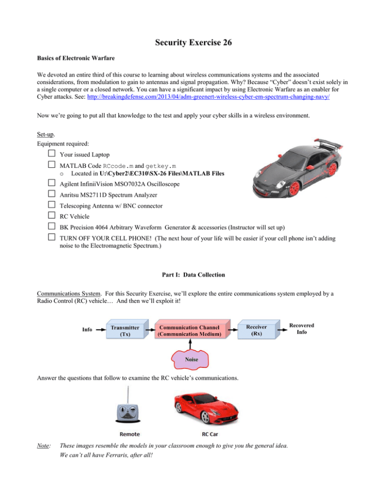
Security Exercise 26 Basics of Electronic Warfare We devoted an entire third of this course to learning about wireless communications systems and the associated considerations, from modulation to gain to antennas and signal propagation. Why? Because “Cyber” doesn’t exist solely in a single computer or a closed network. You can have a significant impact by using Electronic Warfare as an enabler for Cyber attacks. See: http://breakingdefense.com/2013/04/adm-greenert-wireless-cyber-em-spectrum-changing-navy/ Now we’re going to put all that knowledge to the test and apply your cyber skills in a wireless environment. Set-up. Equipment required: □ □ □ □ □ □ □ □ Your issued Laptop MATLAB Code RCcode.m and getkey.m o Located in U:\Cyber2\EC310\SX-26 Files\MATLAB Files Agilent InfiniiVision MSO7032A Oscilloscope Anritsu MS2711D Spectrum Analyzer Telescoping Antenna w/ BNC connector RC Vehicle BK Precision 4064 Arbitrary Waveform Generator & accessories (Instructor will set up) TURN OFF YOUR CELL PHONE! (The next hour of your life will be easier if your cell phone isn’t adding noise to the Electromagnetic Spectrum.) Part I: Data Collection Communications System. For this Security Exercise, we’ll explore the entire communications system employed by a Radio Control (RC) vehicle… And then we’ll exploit it! Answer the questions that follow to examine the RC vehicle’s communications. Note: These images resemble the models in your classroom enough to give you the general idea. We can’t all have Ferraris, after all! Question 1: Which image above (left or right) most closely represents the transmitter? Question 2: Where is the receiver located? Question 3: What type of channel does this communications system involve? Question 4: What do you expect your “information” to be in this case? Question 5: What will happen when the “information” is recovered at the receiver? Question 6: What type of antenna does the transmitter use? Question 7: What would you expect the beam pattern of this antenna to look like? Question 8: Do the transmitter or receiver give any indication of carrier frequency? If so, what is fc? To verify the carrier frequency of the transmitted signal, use the Anritsu MS2711D Spectrum Analyzer. To setup and operate the spectrum analyzer, refer to the sheet titled “SX-26 Equipment Setup Instructions, Part I: Data Collection” posted with the equipment at the lab station. Question 9: What is the carrier frequency? Draw the signal in the frequency domain. Part II: Jamming Now that we have some basic intel, what could happen if your instructor was to transmit a signal at the carrier frequency? The answer: It depends! In lecture, we learned that the effectiveness of electronic attack/jamming is dependent upon the jamming-to-signal Ratio (J/S). The J/S is dependent upon both the power received by the car from the jammer and the transmitter as well as the distance of the jammer and the transmitter from the receiver. In this security exercise, our scenario looks like this: The J/S depends on the received signal power at the car and the received jamming power at the car: æ PJ ö æ Jö çè ÷ø = ç ÷ = PJ (dBm) - PS(dBm) S dB è PS ø dB Generally, if the J/S ratio is greater than 1 (or 0 dB), jamming will be effective. □ Play time! Drive your vehicle around the classroom. Question 10: What two conditions (with regards to frequency and received power) must exist for jamming to be effective? Get your instructor’s signature to continue. □ Your instructor will generate a 20 dBm frequency modulation (FM) signal at the carrier frequency. Question 11: What is your instructor’s target? □ While your instructor is transmitting the jamming signal, experiment! Attempt to control the RC car with its transmitter at different distances from both the jammer and the RC car. Question 12: When your instructor transmitted a jamming signal, were you still able to control the RC car? When could you control it? When couldn’t you? Question 13: Use the Anritsu MS2711D Spectrum Analyzer to draw the jamming signal in the frequency spectrum. How does this change if you transmit while standing next to the Spectrum Analyzer? Question 14: How could you increase the range of the jammer? (How is jamming range dependent on signal power?) Part III: Reverse Engineering So now we know the carrier frequency and the effects of transmitting a higher signal power on that frequency, but if we want to make a bigger impact, we need to know more about the RC car’s signal. What does the transmitted signal look like? What type of modulation does it use? How do controls work? To accomplish this, we’re going to look at the signal using the Agilent Technologies “InfiniiVision” MSO7032A 350 MHz Oscilloscope. First, some initial set-up for the O-Scope. For instructions on setting up and operating the InfiniiVision O-Scope, refer to SX-26 Equipment Setup Instructions, Part III: Reverse Engineering posted with the equipment at the lab station. Once you have the Channel configured, it’s time to Capture the Signal using the Trigger section of the O-Scope. □ □ □ □ □ Press the Edge button Set Source = 1 Ensure the antennas are extended on the O-Scope and the Remote if applicable Holding the RC car transmitter close to the O-Scope, send the Forward signal by driving the car forward. Capture the signal by pressing the Run/Stop button If done correctly, your O-scope display should look similar* to this: * Captured signal may vary – that’s ok for now! Question 15: What type of digital modulation does this car use? Question 16: What pattern of 0s and 1s does the transmitted signal represent? To be able to control the RC car, we want to be able to do more than just drive it forward. How does the signal change for reverse, left, or right? Think about the controls – how many different signals do you expect to control the car? In addition to driving forward, the car can operate in reverse, as well as turning left and right… and any combination thereof! There are actually 8 different combinations of signals, but in the interest of time we’re only going to worry about four: Forward, Reverse, Forward & Right, and Forward & Left. Here’s the catch: the chips that process the signal and control the vehicles motion aren’t necessarily wired the same way in every car, so you need to identify which control operation each transmitted signal represents! Examine each transmitted signal by repeating the process you just followed to Capture the Signal on page 4: □ Press “Run/Stop” button until “Run” lights-up Green □ □ Transmit desired signal, one at a time: o Forward o Reverse o Forward AND Right (This is different from the signal to pivot the wheels to the right only!). o Forward AND Left (This is different from the signal to pivot the wheels to the left only!). As each of the four signals is displayed on the O-Scope screen press “Run/Stop” once, Stop will light Red Question 17: Match the transmitted signals with the operations they represent by circling the correct response. The signals can be distinguished by the number of 1s being transmitted after the 4 large sync pulses. Forward or Reverse or Forward-Right or Forward-Left?? ( # of 1’s: 10) Forward or Reverse or Forward-Right or Forward-Left?? ( # of 1’s: 40) Forward or Reverse or Forward-Right or Forward-Left?? ( # of 1’s: 34) Forward or Reverse or Forward-Right or Forward-Left?? ( # of 1’s: 28) Question 18: Now that you’ve identified the modulated signal that controls the car, could you determine the baseband binary signal (voltage pulses) that are used for each control function? The block diagram for an OOK signal’s generation is shown below. We now know the bits that are transmitted to control the forward, turning, and reverse motions of the RC car. We also know that we can’t transmit the baseband binary signal, so we need to modulate it on a high frequency carrier. If we could reproduce these control signals and transmit by some other means than the car’s remote, do we need the remote to drive the RC car? Let’s find out! Part IV: The Hook In this section, you’ll use the MATLAB code provided and your laptop soundcard to generate and transmit control signals to the RC car. You may have noticed that each transmitted signal consists of 4 wide “sync” pulses followed by a trail of 0’s and 1’s. Since you’ve already matched the waveform to the driving direction, now all you need to do is determine the number of 1’s in the trail following the sync pulses. For example, in the image below represents 01110111011101110101010101010101010101110 in binary (check back to HW23 if you’re not a believer yet – you knew this way back when!). For this sequence of bits, it is organized as follows. On the oscilloscope, the control signal will be displayed as seen in the next figure. Question 19: Fill in the table by entering the number of 1’s trailing the sync pulses for each RC car operation determined in Question 18. You must find the exact value! Direction Number of 1’s in trail Forward Reverse Right N/A Left N/A Fwd-Right Fwd-Left Rev-Right Rev-Left N/A N/A Question 20: Design and sketch a system to “drive” the RC car from your laptop. Your design should include all components of a communications system AND how the modulated signal is achieved. STOP! Your design must be approved by your instructor before continuing! Now that you’ve thought through how to take over the RC car, we’re going to give you an assist with the baseband signal. The MATLAB code below takes input from the arrow keys on your laptop, generates the baseband binary signals to control the RC vehicle, then modulates the signal with OOK. Since we only determined the binary waveform for 4 of the 8 possible operations, we’ll be slightly limited in the operation of our RC vehicle – we won’t be able to turn while operating in reverse. □ In MATLAB, update the “Setup Major Variables” section of your RCcode.m code (shown below) with the number of 1s in the “trail” in preparation of taking over the RC vehicle. %%%%%%%%%%%%%%%% % RC CAR CODE % %%%%%%%%%%%%%%%% %%%%%%%%%%%%%%%%%%%%%%%%%%%%%%%%%%%%%%%%% % % % PRESS SPACE TO TERMINATE EXECUTION % % % %%%%%%%%%%%%%%%%%%%%%%%%%%%%%%%%%%%%%%%%% % % !!!!! NOTE !!!!! % If you do something wrong and Matlab terminates unexpectedly (you get a % lot of angry red Error messages) you will have to close out and restart % Matlab in order to clear out the sound card buffer!!! % % Forward = Up Arrow % Reverse = Down Arrow % Forward Right = Right Arrow % Forward Left = Left Arrow % %%%%%%%%%%%%%%%%%%%%%%%%%%%%%%%%%%%%%%%%%%%%%%%%%%%%%%%%%%%%%%%%%%%%%%%%%% %%%%%%%%%%%%%%%%%%%%%%%%%%%%%%%%%%%%%%%%%%%%%%%%%%%%%%%%%% % Clear out memory and initialize default settings % % DO NOT CHANGE THIS SECTION % %%%%%%%%%%%%%%%%%%%%%%%%%%%%%%%%%%%%%%%%%%%%%%%%%%%%%%%%%% clear all close all set(0, 'DefaultAxesFontSize', 14) set(0, 'DefaultAxesFontWeight','Bold') %%%%%%%%%%%%%%%%%%%%%%%%%%%%%%%%%%%%%%%%%%%%%%%%%%%%%%%%%% Change this Section! %%%%%%%%%%%%%%%%%%%%%%%%%%%%%%%%%%%%%%%%%%%%%%%%%%%%%%%%%% % Setup major variables % % CHANGE THIS SECTION ONLY!!! (FOLLOW LAB INSTRUCTIONS) % %%%%%%%%%%%%%%%%%%%%%%%%%%%%%%%%%%%%%%%%%%%%%%%%%%%%%%%%%% forward_1s = 01; reverse_1s = 01; Insert Number of 1’s from Question 19 table here! right_fwd_1s = 01; left_fwd_1s = 01; %%%%%%%%%%%%%%%%%%%%%%%%%%%%%%%%%%%%%%%%%%%%%%%%%%%%%%%%%% sam_per_sym = 22; %fs/Rb = 44.1e3/(1/Tb), Tb ~ 500us fs = 44.1e3; % Set sampling rate to sound card rate Rb = fs./sam_per_sym; fif = 10e3; % 10.0 kHz "baseband" (IF) Frequency %%%%%%%%%%%%%%%%%%%%%%%%%%%%%%%%%%%%%%%%%%%%%%%%%%%%%%%%%% %%%%%%%%%%%%%%%%%%%%%%%%%%%%%%%%%%%%%%%%%%%%%%%%%%%%%%%%%% % Generate the original data to manipulate the car % % DO NOT CHANGE THIS SECTION % %%%%%%%%%%%%%%%%%%%%%%%%%%%%%%%%%%%%%%%%%%%%%%%%%%%%%%%%%% sync = [1 1 1 0 1 1 1 0 1 1 1 0 1 1 1 0]; forward = [sync repmat([1 0], 1, forward_1s)]; reverse = [sync repmat([1 0], 1, reverse_1s)]; right_fwd = [sync repmat([1 0], 1, right_fwd_1s)]; left_fwd = [sync repmat([1 0], 1, left_fwd_1s)]; pause = zeros(1,500); key = 0; % Initial Keyboard Value %%%%%%%%%%%%%%%%%%%%%%%%%%%%%%%%%%%%%%%%%%%%%%%%%%%%%%% % Reads inputs once per second % % DO NOT CHANGE THIS SECTION % %%%%%%%%%%%%%%%%%%%%%%%%%%%%%%%%%%%%%%%%%%%%%%%%%%%%%%% while key ~= 32 %Press space to stop key = getkey(1); if key == 30 data = [forward forward forward forward forward forward forward forward]; elseif key == 31 data = [reverse reverse reverse reverse reverse reverse reverse reverse]; elseif key == 29 data = [right_fwd right_fwd right_fwd right_fwd right_fwd right_fwd right_fwd right_fwd]; elseif key == 28 data = [left_fwd left_fwd left_fwd left_fwd left_fwd left_fwd left_fwd left_fwd]; else data = [pause]; end % Generate Polar NRZ time_stop = length(data).*sam_per_sym; up_data = zeros(1,time_stop); time = linspace(0,(1/fs).*time_stop, length(up_data)); % Upsample for i = 0:length(data)-1 up_data(sam_per_sym.*i + 1 : sam_per_sym.*i + sam_per_sym) = data(i+1); end % Generate the "baseband" (IF) waveform s_lo = cos(2.*pi.*fif.*time); s_if = s_lo.*up_data; soundsc(s_if,fs) end %%%%%%%%%%%%%%%%%%%%%%%%%%%%%%%%%%%%%%%%%%%%%%%%%%%%%%%% □ □ When your code is updated, run it by pressing (the run button). Follow the next instruction carefully! Double click your cursor in the MATLAB Command Window. If all went as planned you should see a window opening and closing rapidly. □ Press and hold your arrow keys to simulate driving your vehicle. Question 21: What do you hear? What type of signal is being generated? □ Bring your laptop to your instructor and get ready to drive! Question 22: Do you need the car’s transmitter to control the car? What just happened? What is now controlling the car? Question 23: List some examples of how this might be significant in a military setting. Need ideas? Check this out! http://www.engr.utexas.edu/features/humphreysspoofing. EC310 Security Exercise 26 Name: ____________________________________________________________________________________________________ Question 1: ____________________________________________________________________________________________________ Question 2: ____________________________________________________________________________________________________ Question 3: ____________________________________________________________________________________________________ Question 4: ____________________________________________________________________________________________________ Question 5: ____________________________________________________________________________________________________ Question 6: ____________________________________________________________________________________________________ Question 7: ____________________________________________________________________________________________________ Question 8: ____________________________________________________________________________________________________ Question 9: ____________________________________________________________________________________________________ Question 10: __________________________ Instructor/Lab Tech Signature ____________________________________________________________________________________________________ Question 11: ____________________________________________________________________________________________________ Question 12: ____________________________________________________________________________________________________ Question 13: ____________________________________________________________________________________________________ Question 14: ____________________________________________________________________________________________________ Question 15: ____________________________________________________________________________________________________ Question 16: ____________________________________________________________________________________________________ ____________________________________________________________________________________________________ Question 17: Forward or Reverse? # of 1’s ______ Forward or Reverse? # of 1’s ______ Forward-Right or Forward-Left? # of 1’s ______ Forward-Right or Forward-Left? # of 1’s ______ ____________________________________________________________________________________________________ Question 18: ____________________________________________________________________________________________________ Question 19: Direction Forward Reverse Right Left Fwd-Right Fwd-Left Rev-Right Rev-Left Number of N/A N/A N/A N/A 1’s in trail ____________________________________________________________________________________________________ Question 20: __________________________ Instructor/Lab Tech Signature ____________________________________________________________________________________________________ Question 21: ____________________________________________________________________________________________________ Question 22: ____________________________________________________________________________________________________ Question 23: ____________________________________________________________________________________________________
