Document 11118887
advertisement

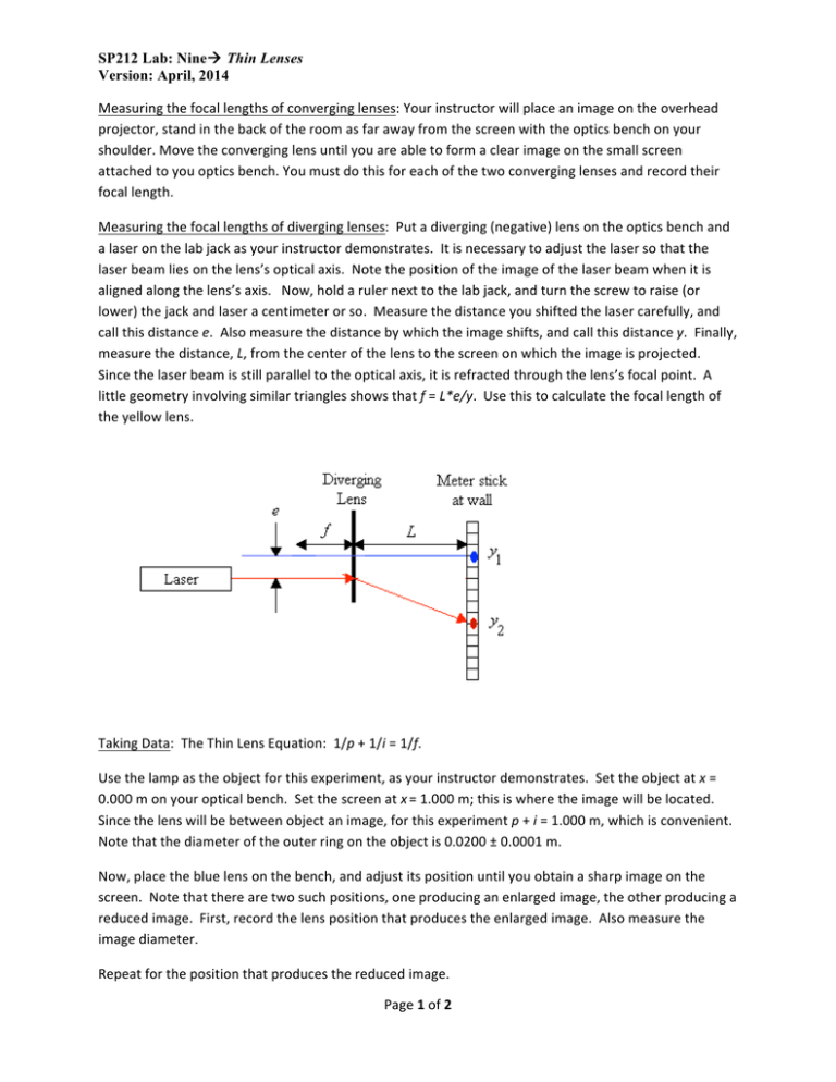
SP212 Lab: Nineà Thin Lenses Version: April, 2014 Measuring the focal lengths of converging lenses: Your instructor will place an image on the overhead projector, stand in the back of the room as far away from the screen with the optics bench on your shoulder. Move the converging lens until you are able to form a clear image on the small screen attached to you optics bench. You must do this for each of the two converging lenses and record their focal length. Measuring the focal lengths of diverging lenses: Put a diverging (negative) lens on the optics bench and a laser on the lab jack as your instructor demonstrates. It is necessary to adjust the laser so that the laser beam lies on the lens’s optical axis. Note the position of the image of the laser beam when it is aligned along the lens’s axis. Now, hold a ruler next to the lab jack, and turn the screw to raise (or lower) the jack and laser a centimeter or so. Measure the distance you shifted the laser carefully, and call this distance e. Also measure the distance by which the image shifts, and call this distance y. Finally, measure the distance, L, from the center of the lens to the screen on which the image is projected. Since the laser beam is still parallel to the optical axis, it is refracted through the lens’s focal point. A little geometry involving similar triangles shows that f = L*e/y. Use this to calculate the focal length of the yellow lens. Taking Data: The Thin Lens Equation: 1/p + 1/i = 1/f. Use the lamp as the object for this experiment, as your instructor demonstrates. Set the object at x = 0.000 m on your optical bench. Set the screen at x = 1.000 m; this is where the image will be located. Since the lens will be between object an image, for this experiment p + i = 1.000 m, which is convenient. Note that the diameter of the outer ring on the object is 0.0200 ± 0.0001 m. Now, place the blue lens on the bench, and adjust its position until you obtain a sharp image on the screen. Note that there are two such positions, one producing an enlarged image, the other producing a reduced image. First, record the lens position that produces the enlarged image. Also measure the image diameter. Repeat for the position that produces the reduced image. Page 1 of 2 SP212 Lab: Nineà Thin Lenses Version: April, 2014 Repeat the experiment (steps a-­‐c above) using the red lens. A combination of lenses: In a multi-­‐lens optical instrument, the lens closest to the object is called the “objective,” and we will call the second lens the “ocular,” or “eyepiece,” even though we will not look through it. Instead we will cast its image on the screen, and observe it there. The image of the objective is the object for the eyepiece, and the overall magnification of the instrument is the product of the magnifications of each lens. The object lamp should still be at x = 0.000 m. Place the red lens on the optical bench at x = 0.200 m. Adjust the screen until you find a nice, sharp image, and record the image location. Also measure and record the image diameter. Use your data to calculate the focal length, and compare with your earlier measurements, and compare the magnifications calculated both ways. Now, place the yellow lens at x = 0.300 m, and adjust the screen to find the image location. Record the image position, and measure and record the image diameter. Use these data to test the lens equation and magnifications as before. Finally, find the product of the individual lens magnifications, and calculate the overall magnification as the ratio of the final image diameter to the original object diameter, and discuss agreement. Page 2 of 2


