Document 11118835
advertisement

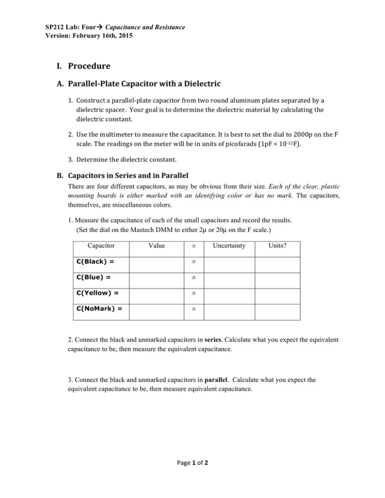
SP212 Lab: Fourà Capacitance and Resistance Version: February 16th, 2015 I. Procedure A. Parallel-­‐Plate Capacitor with a Dielectric 1. Construct a parallel-­‐plate capacitor from two round aluminum plates separated by a dielectric spacer. Your goal is to determine the dielectric material by calculating the dielectric constant. 2. Use the multimeter to measure the capacitance. It is best to set the dial to 2000p on the F scale. The readings on the meter will be in units of picofarads (1pF = 10-­‐12F). 3. Determine the dielectric constant. B. Capacitors in Series and in Parallel There are four different capacitors, as may be obvious from their size. Each of the clear, plastic mounting boards is either marked with an identifying color or has no mark. The capacitors, themselves, are miscellaneous colors. 1. Measure the capacitance of each of the small capacitors and record the results. (Set the dial on the Mastech DMM to either 2µ or 20µ on the F scale.) Capacitor Value ± C(Black) = ± C(Blue) = ± C(Yellow) = ± C(NoMark) = ± Uncertainty Units? 2. Connect the black and unmarked capacitors in series. Calculate what you expect the equivalent capacitance to be, then measure the equivalent capacitance. 3. Connect the black and unmarked capacitors in parallel. Calculate what you expect the equivalent capacitance to be, then measure equivalent capacitance. Page 1 of 2 SP212 Lab: Fourà Capacitance and Resistance Version: February 16th, 2015 C. Resistivity 1. Measure the resistance of the Slinky when the coils are spread apart so that no coils are touching. 2. Calculate the resistivity of the Slinky’s material. Does your answer seem reasonable? 5. Keep one lead on the end of the Slinky. You will move the other end to the (N/4)th coil. Before doing so predict what resistance you expect to measure. Record your prediction (no cheating) and explain your reasoning. Then move the lead to see if your prediction was correct. Record your measurement. Is your prediction consistent with your measurement? If not, explain the holes in your reasoning. 6. With the leads connected to the ends of the Slinky, so that you continue to measure its resistance, set the Slinky on the table and press down so the coils are pressed together. a. What do you observe about the resistance as you do this? Be specific and report values. Explain your observations. b. The length of the conductor is now the height of the Slinky. Measure that height and calculate the effective area that the current travels through. Page 2 of 2


