Active Sonar Equation & Projector Source Level
advertisement

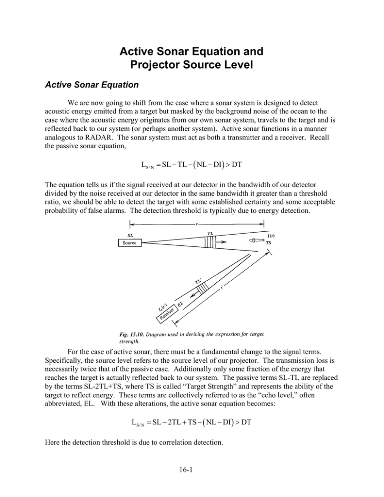
Active Sonar Equation and Projector Source Level Active Sonar Equation We are now going to shift from the case where a sonar system is designed to detect acoustic energy emitted from a target but masked by the background noise of the ocean to the case where the acoustic energy originates from our own sonar system, travels to the target and is reflected back to our system (or perhaps another system). Active sonar functions in a manner analogous to RADAR. The sonar system must act as both a transmitter and a receiver. Recall the passive sonar equation, LS/ N = SL − TL − ( NL − DI ) > DT The equation tells us if the signal received at our detector in the bandwidth of our detector divided by the noise received at our detector in the same bandwidth it greater than a threshold ratio, we should be able to detect the target with some established certainty and some acceptable probability of false alarms. The detection threshold is typically due to energy detection. For the case of active sonar, there must be a fundamental change to the signal terms. Specifically, the source level refers to the source level of our projector. The transmission loss is necessarily twice that of the passive case. Additionally only some fraction of the energy that reaches the target is actually reflected back to our system. The passive terms SL-TL are replaced by the terms SL-2TL+TS, where TS is called “Target Strength” and represents the ability of the target to reflect energy. These terms are collectively referred to as the “echo level,” often abbreviated, EL. With these alterations, the active sonar equation becomes: LS/ N = SL − 2TL + TS − ( NL − DI ) > DT Here the detection threshold is due to correlation detection. 16-1 Active sonar is more complicated than the passive case because as an emitter of acoustic energy, our system adds to the background noise masking the reflected signal. This is particularly true if there are other non-target items that reflect sound back to our system at about the same time as the target reflection is detected. Possible sources of reflection are the surface and bottom, fish, other biologics, air bubbles, and dust or dirt. LS/ N = SL − 2TL + TS − RL > DT These reflections are in combination referred to as reverberation. The term that describes the ability of these unwanted reflections to mask the target signal is called “Reverberation Level.” The first active sonar equation is the case when the received noise level only limits the detectability of the return reflection from the target. The second is used when reverberation of the outgoing pulse, limits the detectability of the return reflection. We will discuss these equations further during the next few weeks. Unfortunately, much like income tax calculations, there is often no way to know which method to use until both calculations are done and we see which is more limiting. Projector Source Level Before we delve further into the active sonar equation though, let’s start with a revisit and redefinition of the source level term, SL. In the active sonar equation, the source level is no longer the level of the contact or target, but rather the source level of the projector from the active sonar system. This source level is the level (in dB re 1µPa) of the projector, 1 yard from the projector. To solve for the source level, we can start with the definition of passive source level: I1yd SL = 10 log I ref Substituting in the equation for intensity: p2 Pwr I1 yd = rms = ρc Area at 1 yd where Area at 1 yd = 4π (1 yd ) 2 so the SL becomes: ⎛ ⎞ ⎜⎜ Pwr 2⎟ 4π (1 yd ) ⎟⎠ Pwr ⋅ρc = 10 log SL = 10 log ⎝ 2 2 ⎛ p ref ⎞ 4π (1 yd ) p 2ref ⎜ ρc ⎟⎠ ⎝ 16-2 We can substitute in the nominal values for the density and speed of sound of seawater (ρSW=1000 kg/m3 and cSW=1500 m/s), knowing pref=1µPa and converting yards to meters we get: 1000 kg/m3 ) (1500 m/s ) ( SL = 10 log ( Pwr ) + 10 log 2 2 2 4π (1 yd ) 0.9144 m 1x10⁻⁶ Pa ) ( 1 yd ( ) SL = 10 log ( Pwr ) + 171.5 dB Within the sonar system, there is an efficiency at converting the electrical input power to the acoustical output power and this can further modify our results where: Pwracoustic = PE ⋅ E where E is the system efficiency thus: SL = 171.5 dB + 10 log ( PE ⋅ E ) SL = 171.5 dB + 10 log PE + 10 log E BUT, this is only for an omni-directional hydrophone. We must now account for the directionality of our transducer. Directionality of Transducer Our latest result assumes that the active source is omni directional (all power is transmitted equally in all directions.) An omni-directional transducer is nearly impossible to build though and may not be the best option. To account for the directionality of the transducer, we must add in a directionality term, DIT, the directivity index for the active transducer. The directivity index is defined as it was for the passive sonar equation, the only difference is that the intensities would now be the intensities of the active transmission from the transducer. I DIT = 10 log non −directional Idirectional A well known theorem in acoustics called the Principle of Reciprocity states as one of its conclusions that under certain conditions the beam pattern b(θ,φ) of a receiving array is the same as that for a transmitting array. This means that the receiving directional properties of n-element arrays, line arrays, and circular piston arrays will be useful in describing the directional properties of transmitting arrays. We can show that the source level of the sound within the main beams of the transducer becomes: SL = 171.5 dB + 10 log PE + 10 log E + DIT Just as passive directivity index prevented us from listening to noise from unimportant directions and effectively reducing the noise, transmitting directivity index prevents us from directing sound into unwanted directions, effectively increasing the source level. 16-3 Transducer Sensitivity We next define transducer sensitivity. This quantifies the quality of the electro-acoustic conversion. It expresses the relation between the input and output values of the transducer (acoustic pressure to electric voltage). ⎛I ⎞ ⎛p ⎞ SV = 10 log ⎜ 1V ⎟ = 20 log ⎜ 1V ⎟ ⎝ I ref ⎠ ⎝ p ref ⎠ Where p1v is the acoustic pressure 1 m away from the transducer in a given direction for a voltage of 1 V. V2 For an input voltage of 1 V, recalling that electric power, PE = , we get: R SL = SV = 171.5 − 10 log R P + 10 log E + DI Where RP is the real part of the input electrical impedance. Manufacturers typically use SV to allow consumers to compare systems with the same 1 V input. To convert SV to actual SL, simply add 20logV. Acoustic Cavitation The maximum transmission power is limited by two physical constraints: 1. If too large a voltage is applied to the transducer, it leads to a non-linear response of the materials, followed by degradation and failure. 2. Limits of the propagation medium – cavitation. Cavitation occurs when the local low pressure caused by the acoustic pressure wave causes gas bubbles to form in front of the transducer, thereby limiting the electro-acoustic efficiency. The bubbles act as little shock absorbers damping effect of the motion of the transducer face on the surrounding water. This effect doesn’t occur when the acoustic pressure on the projector wall is greater than or equal to pcav. p cav = p atm + 104 z , where z is depth in meters In terms of power that causes cavitation: Pcav = S p cav 2 2ρc , where S is transmitting surface Therefore: SLcav = 186 + 10 log S + DI + 20 log (10 + z ) 16-4 Problems 1. Given the peak electric power of an active sonar system as 850 W, system efficiency as 27%, IND = 1, and ID = 18, determine: a) The Source Level? b) The acoustic power level? 2. A sound projector is a plane circular piston of diameter 50 cm and operates at a frequency of 15 kHz with a power output of 2500 W. The speed of sound is 1500 m/s. a) What is the source level of the projector on the beam axis b) What is the plane wave rms acoustic pressure at one yard from the acoustic center (i.e. on the beam axis)? 3. An acoustic homing torpedo transducer is a plane circular array of diameter 25 cm. It operates at 15 kHz in water where c = 1500 m/s. If the efficiency of converting electrical energy into acoustic energy is 60%, and a source level of 220 dB is required, what must be the electric power input? 16-5 Lesson 16 Active Sonar Equation Adapting Passive Ideas LS/ N = SL − TL − ( NL − DI ) > DT Passive Case: TL + TL ' ≈ 2TL From our Sonar Target Strength describes the fraction of energy reflecting back from the target LS/ N = SL − 2TL + TS − ( NL − DI ) > DT Reverberation Noise Active Sonar – Materials • Typical piezoelectric materials Reflections from non-target objects is greater that noise. – Quartz – PZT -Lead zirconate titanate – Barium Titanate Reverberation limited RL > NL − DI LS/ N = SL − 2TL + TS − RL > DT Source Level for an Omnidirectional projector Piezoelectricity SL = 10 log a I1 yd = I 1 yd I ref p 2rms Pwr = ρc Area at 1 yd where Area at 1 yd = 4π (1 yd ) a+∆a 2 ⎛ ⎞ Pwr 2⎟ ⎜⎜ 4π (1 yd ) ⎟⎠ Pwr ⋅ρc = 10 log SL = 10 log ⎝ 2 ⎛ p 2ref ⎞ 4π (1 yd ) p 2ref ⎜ ⎟ ρ c ⎝ ⎠ SL = 10 log ( Pwr ) + 10 log (1000 kg/m ) (1500 m/s ) 4π (1 yd ) ( 0.9144 m 1x10 1 yd ) ( 3 2 2 −6 Pa ) 2 = 10 log ( Pwr ) + 171.5 dB 1 Lesson 16 Electrical Efficiency Directional Arrays PwrElectric DIT = 10 log Pwracoustic = PwrElectric ⋅ E where E is the system efficiency thus: Principle of Reciprocity SL = 171.5 dB + 10 log ( PE ⋅ E ) Pwracoustic I non − directional I directional b ( θ, φ ) receiving = b ( θ, φ )Transmitting SL = 171.5 dB + 10 log PE + 10 log E SL = 171.5 dB + 10log PE + 10 log E + DIT Efficiency may range from 20% to 70% for most sonar applications Transducer Sensitivity How many dB for 1 volt input? • Compute the source level for an circular piston projector of diameter = 1 meter radiating 10 kW acoustic power at a frequency of 15 kHz in water ⎛I ⎞ ⎛p ⎞ SV = 10 log ⎜ 1V ⎟ = 20 log ⎜ 1V ⎟ ⎝ I ref ⎠ ⎝ p ref ⎠ SL = 171.5 dB + 10log PE + 10 log E + DIT V2 R PE = Example ⎛ π (1m ) ⎞ ⎛ πD ⎞ DIT = 10 log ⎜ ⎟ = 29.94dB ⎟ = 10 log ⎜ ⎝ λ ⎠ ⎝ .1m ⎠ 2 SL ( @1V ) = SV = 171.5 − 10log R P + 10 log E + DI Input impedance Piston array: 2 SL = 171.5 dB + 10log104 + 29.94 dB = 241.5 dB Manufacturers typically advertise based on SV. To find SL, add 20logV. Cavitation Pressure Threshold Power Threshold pcav = patm + 10 4 z Pcav = S pcav (z in meters) 2 2ρ c S = Tranducer Surface Area SLcav = 186 + 10 log S + DI + 20 log (10 + z ) 2


