ω
advertisement
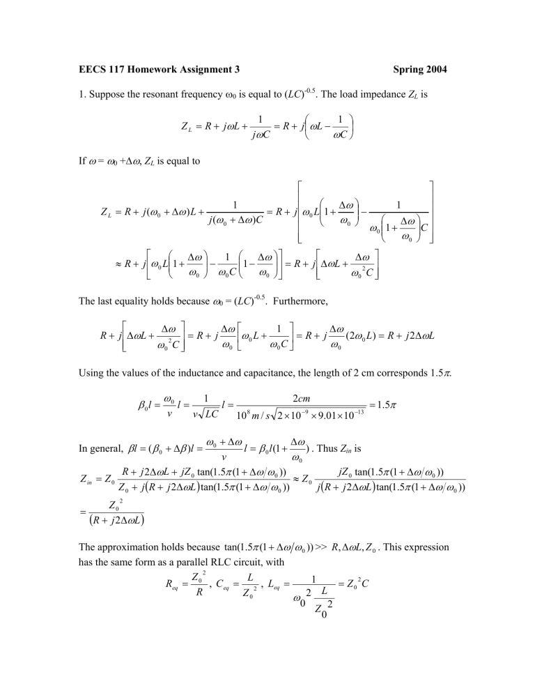
EECS 117 Homework Assignment 3 Spring 2004 1. Suppose the resonant frequency ω0 is equal to (LC)-0.5. The load impedance ZL is Z L = R + jω L + 1 1 = R + j ωL − jωC ωC If ω = ω0 +∆ω, ZL is equal to ∆ω 1 1 − Z L = R + j (ω 0 + ∆ω ) L + = R + j ω 0 L1 + ω j (ω 0 + ∆ω )C ∆ω 0 C ω 0 1 + ω 0 ∆ω 1 ∆ω ∆ω − 1 − = R + j ∆ωL + 2 ≈ R + j ω 0 L1 + ω 0 ω 0 C ω 0 ω 0 C The last equality holds because ω0 = (LC)-0.5. Furthermore, ∆ω 1 ∆ω ∆ω (2ω 0 L) = R + j 2∆ωL R + j ∆ωL + 2 = R + j ω 0 L + = R+ j ω0 ω0C ω0 ω 0 C Using the values of the inductance and capacitance, the length of 2 cm corresponds 1.5π. β 0l = ω0 v l= 1 v LC In general, β l = ( β 0 + ∆β )l = l= 2cm 10 8 m / s 2 × 10 −9 × 9.01 × 10 −13 ω 0 + ∆ω l = β 0 l (1 + = 1.5π ∆ω ) . Thus Zin is ω0 v R + j 2∆ωL + jZ 0 tan(1.5π (1 + ∆ω ω 0 )) jZ 0 tan(1.5π (1 + ∆ω ω 0 )) Z in = Z 0 ≈ Z0 Z 0 + j (R + j 2∆ωL ) tan(1.5π (1 + ∆ω ω 0 )) j (R + j 2∆ωL ) tan(1.5π (1 + ∆ω ω 0 )) 2 Z0 = (R + j 2∆ωL ) The approximation holds because tan(1.5π (1 + ∆ω ω 0 )) >> R, ∆ωL, Z 0 . This expression has the same form as a parallel RLC circuit, with 2 Z L 2 1 = Z0 C Req = 0 , C eq = 2 , Leq = L R Z0 ω 2 0 Z 2 0 Therefore, the input impedance Zin is that of a second order circuit. Also, LeqCeq = LC = ω0-2, so our assumption is correct, i.e., ω0 = (LC)-0.5. The Q factor is Q = ω 0 Req C eq = L R LC = L R = 94 C The equivalent circuit is Leq = Z02C = 5 µF, Ceq = L/Z02 = 0.3604 fH, and Req = Z02/R = 1250 in parallel. 2. For a lossy line, the input impedance has a form Z in = Z 0 Z L + jZ 0 tanh(αl + jβ l ) Z 0 + jZ L tanh(αl + jβ l ) where ZL = 2j∆ωL. Also, tanh(αl + jβl ) = sinh(2αl ) sin(2β l ) + j cos(2β l ) + cosh(2αl ) cos(2β l ) + cosh(2αl ) sin(2 βl ) = sin(3π (1 + ∆ω / ω 0 )) ≈ sin(3π ) + cos(3π ) * (3π∆ω / ω 0 ) = −3π∆ω / ω 0 . Likewise, cos(2βl ) ≈ cos(3π ) − sin(3π ) * (3π∆ω / ω 0 ) = −1 . So, tanh(αl + jβ l ) = 3π∆ω / ω 0 sinh( 2αl ) −j cosh(2αl ) − 1 cosh(2αl ) − 1 The input impedance is then equal to sinh( 2αl ) 2 j∆ωL + jZ 0 − cosh(2αl ) − 1 Z in = Z 0 sinh( 2αl ) − Z 0 + j 2 j∆ωL cosh(2αl ) − 1 j 3π∆ω / ω 0 cosh(2αl ) − 1 j 3π∆ω / ω 0 cosh(2αl ) − 1 3π∆ω / ω 0 sinh( 2αl ) + j 2∆ωL + Z 0 cosh(2αl ) − 1 cosh(2αl ) − 1 = Z0 3π∆ω / ω 0 sinh( 2αl ) Z 0 − 2∆ωL + j 2∆ωL cosh(2αl ) − 1 cosh(2αl ) − 1 Z 3π∆ω / ω 0 + j (2∆ωL(cosh(2αl ) − 1) + Z 0 sinh( 2αl ) ) ≈ Z0 0 Z 0 (cosh(2αl ) − 1) − 2∆ωL sinh( 2αl ) Z0 The third term in the denominator has ∆ω2 dependence and is thus negligible. 4. This problem is similar to the example 3-16 in the textbook. For matching of the load with either a short or an open shunt stub, we have the following circuit: Ytot,in βl A Z0 ZL ZM βl’ Yin Where ZM is either 0 or infinity for a short or an open stub, respectively. Since we are dealing with shunt stub, admittance would simplify the calculation. The equivalent admittance at point A (excluding the stub for a moment) is given by Yin = Y0 YL + jY0 tan( β l ) Y0 + jYL tan( β l ) where Y0 = [Z0]-1= 1/50, and YL = [Z0]-1= 1/100 + j3/100. Separating the expression into the real and imaginary parts gives 1 + x2 3x 2 − 3x − 3 Yin = + j (10 + 15 x) 2 + 25 x 2 (10 + 15 x) 2 + 25 x 2 where x = tan(βl). Since a short or an open stub can behave as a purely reactive element, the real part of Yin above should be equal to Z0 in order for the matching to take place. Thus, we have, 1 + x2 1 = Y0 = 2 2 (10 + 15 x) + 25 x 50 −3− 5 −3+ 5 or . Both of them are 4 4 negative. This means that βl is larger than π/2. The more negative value represents a point closer to the load and this value will be used in the following calculation. The solution of this equation is: tan(βl) = tan(βl) = −3− 5 ⇔ βl = 2.22315. 4 Substitute this value into the imaginary part of Yin and get j 3x 2 − 3x − 3 (10 + 15 x ) 2 + 25 x 2 = 0.044721 j x= − 3− 5 4 The stub needs to have an impedance opposite to the value above in order to cancel the reactive part of the Yin for matching. For a short stub, Y = − jY0 cot( β l ' ) . Therefore, we want 0.044721 = cot( β l ' ) ⇔ βl’ = 0.420534. Y 0 The input impedance at point A including the stub is Ytot ,in 1 + tan 2 (2.22315) = (10 + 15 tan(2.22315) )2 + 25 tan 2 (2.22315) 3 tan 2 (2.22315) − 3 tan(2.22315) − 3 Y0 − + j 2 2 tan( 0 . 420534 ) ( ) + + 10 15 tan( 2 . 22315 ) 25 tan ( 2 . 22315 ) The imaginary part is equal to zero. The SWR is given by 1+ Y0 − Yin Y0 + Yin 1− Y0 − Yin Y0 + Yin S= In general, for β’ ≠ β, i.e., β’l = βl*n, where n is the ratio of β’ to β, the input impedance shown above is 1 + tan 2 (2.22315n) Ytot ,in (n) = (10 + 15 tan(2.22315n) )2 + 25 tan 2 (2.22315n) 3 tan 2 (2.22315n) − 3 tan(2.22315n) − 3 Y0 − + j 2 2 n tan( 0 . 420534 * ) ( ) + n + n 10 15 tan( 2 . 22315 ) 25 tan ( 2 . 22315 ) and the SWR is equal to 1+ Y0 − Yin (n) Y0 + Yin (n) 1− Y0 − Yin (n) Y0 + Yin (n) S= SWR can be plotted as a function of n, representing the amount of shift in the signal frequency / phase constant from the ones used in calculating the numbers above. S 1.4 1.3 1.2 1.1 0.98 0.99 n 1.01 The values of n where S = 1.2 are 0.989 and 1.01, for a short stub. Following the same procedure, we have these for an open stub Y = jY0 tan( β l ' ) ⇔ 0.044721 = − tan( βl ' ) ⇔ βl’ = 1.99133. Y0 1.02 1 + tan 2 (2.22315n) Ytot ,in (n) = (10 + 15 tan(2.22315n) )2 + 25 tan 2 (2.22315n) 3 tan 2 (2.22315n) − 3 tan(2.22315n) − 3 − + j tan( 1 . 99133 * Y n 0 2 2 ( ) + + 10 15 tan( 2 . 22315 ) 25 tan ( 2 . 22315 ) n n The plot of S vs. n: S 1.7 1.6 1.5 1.4 1.3 1.2 1.1 0.98 0.99 1.01 n 1.02 The values of n where S = 1.2 are 0.993 and 1.01. For impedance matching with a lumped element, we have the following circuit: βl Z0 ZM ZL To keep the problem simple, let’s make the lumped element ZM a purely reactive component. With this constraint, the real part of Yin needs to match the characteristic impedance of the transmission line, just like the cases of short and open stubs above. The previous calculation gives β l = 2.22315 or 2.95288 . Just as before, we pick the shortest distance β l = 2.22315 . At this length, Yin is equal to Yin = 0.02 + 0.0447214 j The positive imaginary part implies that the lumped element needs to be an inductor in order to make the impedance matching work. So, YM = 1 Z M = − j (ωL) = − j /( β vL) = −0.0447214 j where v is the propagation velocity of the transmission line. The velocity is property of the transmission line, and does not depend on the signal frequency. In general, Ytot,in is 1 + tan 2 (2.22315n) Ytot ,in (n) = (10 + 15 tan(2.22315n) )2 + 25 tan 2 (2.22315n) 3 tan 2 (2.22315n) − 3 tan(2.22315n) − 3 0.04427214 + j − 2 2 n (10 + 15 tan(2.22315n) ) + 25 tan (2.22315n) The plot of S vs. n: S 1.4 1.3 1.2 1.1 0.98 0.99 n The values of n where S = 1.2 are 0.989 and 1.01. 1.01 1.02 In summary, Bandwidth for S ≤ 1.2 Short 0.989 ω0 to 1.01 ω0 Open 0.993 ω0 to 1.01 ω0 Lumped 0.989 ω0 to 1.01 ω0
