Document 11088896
advertisement

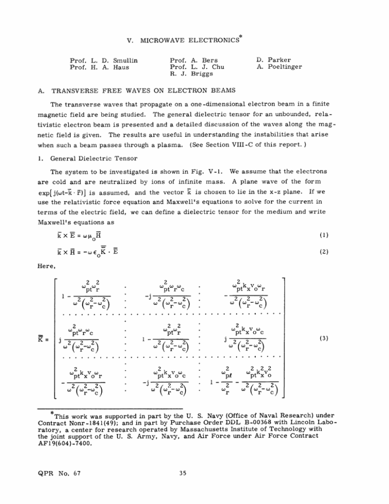
V. MICROWAVE ELECTRONICS A. D. Parker A. Poeltinger Prof. A. Bers Prof. L. J. Chu R. J. Briggs Prof. L. D. Smullin Prof. H. A. Haus TRANSVERSE FREE WAVES ON ELECTRON BEAMS The transverse waves that propagate on a one-dimensional electron beam in a finite magnetic field are being studied. The general dielectric tensor for an unbounded, relativistic electron beam is presented and a detailed discussion of the waves along the magnetic field is given. The results are useful in understanding the instabilities that arise (See Section VIII-C of this report. ) when such a beam passes through a plasma. 1. General Dielectric Tensor We assume that the electrons The system to be investigated is shown in Fig. V-l. A plane wave of the form are cold and are neutralized by ions of infinite mass. exp[j(wt-k - F)] is assumed, and the vector k is chosen to lie in the x-z plane. If we use the relativistic force equation and Maxwell's equations to solve for the current in terms of the electric field, we can define a dielectric tensor for the medium and write Maxwell's equations as kXE= (1) LoH (2) kXH=-EEoK.E Here, 1- r J -j 22 2 w.kw e 2 Wpt rWc 2_ 22 2 2r Wpt r c 2 2(2 2 2 Wpt r 1- 2 r c WPtkxVoO e 2) 2 c 2 2 pt x or 2( 2 pt x o r 2 2 2 Wpt r 2 r 2) c Wpt x 0oc -j W2(w2 \r )2 c) i Z W. 2 222 pt kxo 0 2r- W2 c) r This work was supported in part by the U. S. Navy (Office of Naval Research) under Contract Nonr-1841(49); and in part by Purchase Order DDL B-00368 with Lincoln Laboratory, a center for research operated by Massachusetts Institute of Technology with the joint support of the U. S. Army, Navy, and Air Force under Air Force Contract AFI9(604)-7400. QPR No. 67 (V. MICROWAVE ELECTRONICS) w r =w-k v zo lel B0 c mt 2 ep 0 pt- 2 pi and (4) Comt epo - E mp po is the charge density of the beam as measured by a stationary observer. The transverse and longitudinal masses are defined by mt = Yomo m 3 = ymo , where v2/c2 yo= (Iand to m0 is include the rest a 1/2 mass. multiparticle The dielectric system by tensor can easily be summing over all manner. X k z B0 k= k i +k xx Fig. V-1. QPR No. 67 i Z Z Electron-beam system. species generalized in the usual (V. 2. MICROWAVE ELECTRONICS) Waves along the Magnetic Field For the waves along the magnetic field, k x = 0 and the dielectric tensor assumes the form K -K I. 0 x SKx K 0 0 0 K where the elements are easily obtained from the general tensor. types (in the rest of this report, The waves are of two k z = k): (a) Longitudinal oscillations with H = 0 and E = E z ; K 11 = 0. These are the well- known space-charge waves and will not be discussed further in this investigation. (b) Transverse waves that are right or left circularly polarized with 2 2 k=-- K for left polarization (clockwise) (6) c 2 2 2 k c (7) 2_Kr for right polarization (counterclockwise) where K =K 2 Wpt r 2 - jKx = 1 (8) 2 pt r Kr K. + jK x = 1 2 (9) r c The solutions of the dispersion equations are complicated because of their cubic nature. The propagating modes are most easily obtained by a transformation into a reference frame moving with the beam because the dispersion equation is then quadratic (Fig. V-2). The transformation of (w, k) is w= Yo(w' + k'v o ) k = -o(k' + u'vo/c QPR No. 67 (10) 2 ). (11) (V. MICROWAVE ELECTRONICS) XI x V Z y CO-MOVING FRAME LABORATORY FRAME Fig. V-2. Co-moving reference frames. In the primed reference frame, the dispersion equations are wo2 k' 2 2 p - - (left) (+co c (12) co where epo 2 p 2 E0 pt 00 (14) eB W co and p' =- is m o = lYW oc the charge density as measured in the co-moving reference It should be noted that Eqs. The dis- the left and right circularly polarized waves in an electron plasma. persion of the right polarized left polarized case; frame. 12 and 13 are just the dispersion relations for waves can be obtained by letting w - -w in the thus a plot of w-k for positive and negative frequencies for the left polarized waves will cover both cases in the primed reference frame. If we have reasonably low densities dispersion equation is of the and high magnetic form sketched in Fig. V-3. fields ( <<w co), the The transformation to the laboratory frame gives the dispersion curve shown in Fig. V-4. We notice that the left polarized wave has a low-frequency backward wave under QPR No. 67 Fig. V-3. Dispersion of left polarized wave in co-moving frame (w <<wco). p co I LJ V 0 Ld C LEFT - POLARIZED RIGHT -POLARIZED V Fig. V-4. QPR No. 67 Electron-beam dispersion (wp<<w ). pc W Vo Pt c 2 o c c Fig. V-5. Detail of low-frequency, backward wave valid if -wC c 1 .< 380 > - 0 s 3O REAL k Y (kCOMPLEX k RICHT - POLARIZED 2 Fig. V-6. QPR No. 67 Dispersion for 2 Vo = Wco coo c p 0.5. MICROWAVE ELECTRONICS) (V. in This branch conditions. these the next phase velocities is active an c. less than backward wave a Therefore, negative that propagates negative of the portion It Fig. V-5. wave carries left polarized that the section detail in shown in is will be energy low-frequency energy opposite shown for all branch to the beam velocity. LEFT- POLARIZED 2 0 2 \ 3 4 co0 (k ___Re > COVFLEX 3 RIGHT- < POLAFIZED 2 0 I 2_ w-k plots approximate formation to analysis gives obtain the root. These for at least complex are some are also k 4 3 Dispersion for Fig. V-7. The _ co 2 = 10 p 2 o - 0. 5. o , co c cases that representative shown in Figs. V-6, V-7, k for all values from Eqs. 6 and 7 one real shown in root of Figs. V-6, V-7, and are not covered and V-8. w, it is Since a by factoring V-8. It by this the trans- simple out the can be matter real shown that the low-frequency backward wave will no longer exist when (wp/wc)(Vo/c) exceeds a certain critical value of the order of unity. V-7, and V-8. QPR No. 67 This is also evident from Figs. V-6, (V. MICROWAVE ELECTRONICS) 0 >3 0 ° 3 LEFT - POLARIZED .025 0.5 0 .05 Wco 3 -0.52 REAL k -_ --- Re (k) Re- (k) Im (k)J --- COMPLEX k RIGHT - POLARIZED > 03 01 3 Dispersion for w Fig. V-8. 3. 2 p 10ow 2 CO , Vo C 0. 1. Energy and Power The application of Sturrock's criterion would show that the left polarized waves with phase velocity less than c carry negative energy, whereas the right polarized waves carry positive energy.1 This can also be shown from an explicit evaluation of the energy density in the laboratory frame. such a medium is W = 1/4 i 2 The total energy density of a plane wave in ' 3 =22 + 1/4 -* E - 0 = (wK)E. - (15) It can be shown that the right and left polarized waves are orthogonal, and that the energy density of the left polarized wave is QPR No. 67 (V. W = 1/4 io Ti 2 MICROWAVE ELECTRONICS) + 1/4 E I1 28 (wK2 ) 2 Wpt c 1/4 = Eo0 2 2 w(w-kv + For a slow wave, w/k < c, it can be shown that for propagating waves the wave number must lie in the range w+w <k c < o o By using the disperion relations, the energy density can be written as 2 + 2w(w-kvo) W =- 1/4 EIE12 + 2kcw(1 - (w-kc) w(kv o - w) (w+wc-kv o which is negative definite for slow waves. ) The energy density of the right polarized wave is Wr = 1/4 Wr Eo 22 + o(o kptw c)2 which is positive definite. R. J. Briggs, A. Bers References 1. P. A. Sturrock, In what sense do slow Phys. 31, 2052-2056 (1960). 2. A. Bers, Properties of waves in timeProgress Report No. 65, Research Laboratory pp. 89-93. 3. A. Bers, Energy and power in media Quarterly Progress Report No. 66, Research July 15, 1962, pp. 111-116. QPR No. 67 waves carry negative energy? J. Appl. and space-dispersive media, Quarterly of Electronics, M. I. T., April 15, 1962, with temporal and spacial dispersion, Laboratory of Electronics, M.I. T.,


