I. PHYSICAL ELECTRONICS S. Aisenberg
advertisement
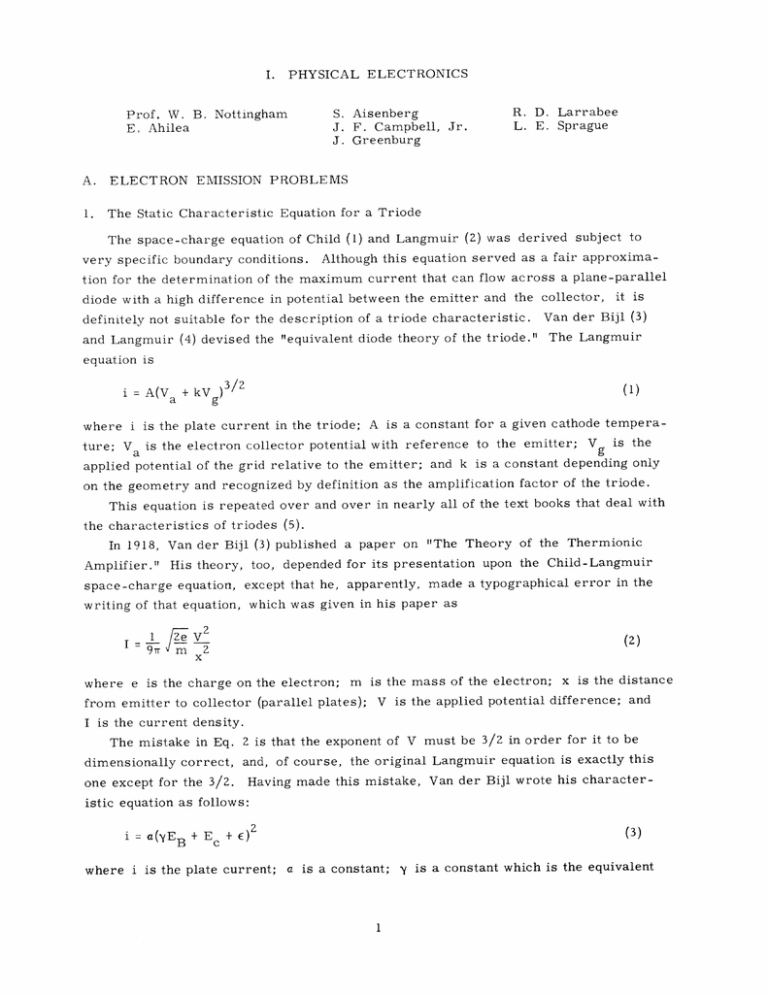
PHYSICAL ELECTRONICS I. S. Aisenberg J. F. Campbell, Jr. J. Greenburg Prof. W. B. Nottingham E. Ahilea A. ELECTRON EMISSION PROBLEMS 1. The Static Characteristic Equation for a Triode R. D. Larrabee L. E. Sprague The space-charge equation of Child (1) and Langmuir (2) was derived subject to very specific boundary conditions. Although this equation served as a fair approxima- tion for the determination of the maximum current that can flow across a plane-parallel diode with a high difference in potential between the emitter and the collector, it is definitely not suitable for the description of a triode characteristic. and Langmuir (4) devised the "equivalent diode theory of the triode." Van der Bijl (3) The Langmuir equation is (1) + kV )32 g = i A(V iA(V where i is the plate current in the triode; A is a constant for a given cathode temperature; Va is the electron collector potential with reference to the emitter; Vg is the applied potential of the grid relative to the emitter; and k is a constant depending only on the geometry and recognized by definition as the amplification factor of the triode. This equation is repeated over and over in nearly all of the text books that deal with the characteristics of triodes (5). In 1918, Van der Bijl (3) published a paper on "The Theory of the Thermionic Amplifier." His theory, too, depended for its presentation upon the Child-Langmuir space-charge equation, except that he, apparently, which was given in his paper as writing of that equation, I IZe i, V made a typographical error in the 2 (2) where e is the charge on the electron; m from emitter to collector (parallel plates); is the mass of the electron; x is the distance V is the applied potential difference; and I is the current density. The mistake in Eq. 2 is that the exponent of V must be 3/2 in order for it to be dimensionally correct, and, of course, the original Langmuir equation is exactly this one except for the 3/2. Having made this mistake, Van der Bijl wrote his character- istic equation as follows: i = a(yE B + E c +E) 2 where i is the plate current; (3) a is a constant; y is a constant which is the equivalent (I. PHYSICAL ELECTRONICS) of the 1/k of Langmuir's equation; E B is the applied potential of collector relative to emitter; E C is the applied potential of grid relative to emitter; and E is a constant. Van der Bij1 found that his equation was in satisfactory agreement with experiment, but between the time of its publication in 1918 and the writing of his book in 1920 (6) he apparently realized the error of his derivation and described his equation as one that was "determined empirically" and for which there is no derivation. No books or papers that have come to my attention attempt to derive this equation on the basis of the most important physical fact concerning triodes - that their operation depends upon the actual modulation of the space-charge minimum by the variation of the potential applied to the grid or to the plate in the triode. Practical tubes with indirectly heated cathodes are not ideal structures for the application of the true spacecharge equations developed specifically for the planar diode. However, since the distance from the emitter to the space-charge minimum is generally small compared with the radius of the curvature of the emitter, the basic equations (7) often apply with remarkable accuracy. In this manner the following equation for the transconductance of a triode was derived (8): gm = ai -V g 3. 51 x 108 1/2 (4) V1/4 A1/2 T where gm is the transconductance; i is the plate current in triode; Cg is the true capacity coefficient (in farads) between grid wires and cathode (not the input capacity but approximately 20 per cent of it, depending on the tube structure); A is the area of the cathode (in m 2 ); and VT is voltage equivalent of cathode temperature or 11, 600/T. Equation 4 may be integrated and solved for the plate current to give i1 / 2 3. 51 X 108 C V g (Ec + yEB + E) c 2V1/4 A1/2 T (5) Equation 5 is in exactly the same form as the Van der Bijl empirical equation given above as Eq. 3. The constant of integration was written as (yEB + E) to take into account the well-known fact that to a high degree of accuracy the amplification factor = (l/y) is a constant dependent only on geometrical factors over a very wide range of operating conditions. j. Equations 4 and 5 may be easily tested from data obtainable in the various tube manuals by plotting the transconductance as a function of the square root of the plate current. For the second equation, the square root of the plate current may be plotted as a function of the grid potential for a constant plate voltage or as a function of plate voltage for a constant grid potential. Figure I-1 shows two of many plots of this kind (I. TUBE TUBE --- 6 SN7 6 AD 7 PHYSICAL ELECTRONICS) -0-0- E 8 = 150 VOLTS E 2 / / / / / / /0 -30 -25 / 0/ 0 / / -20 -15 -10 -5 0 GRID VOLTS Fig. I-i. made for practical tubes. Two examples of a test of Eq. 5, of the RCA Tube Handbook. from data The data agree remarkably well over a very wide range of working parameters and therefore justify the use of Eq. 6 as the characteristic equation for a triode in preference to the Langmuir equation (Eq. 1), which is now so generally used. i = K (1 Ec + E B + where K = 3.51 x 10⁸ Cg) E)2 z1/4 A1/2 Either Eq. 5 or Eq. 6 may be differentiated to obtain an equation for the plate resistance, which is defined as the change in plate potential per unit change in plate current with the grid potential constant. R 1v/4 A1/Z 1 -- T 3.51 X 10 Cg /Z 3.51X10⁸ C i1/2 gi1 This equation is (I. PHYSICAL ELECTRONICS) Equation 7 can also be tested by plotting the plate resistance of the triode as a function of iW. B. Nottingham References 1. C. D. Child, Phys. Rev. 32, 2. I. Langmuir, Phys. 3. H. J. 4. I. Langmuir, Proc. 5. Typical references are: E. L. Chaffee, Theory of Thermionic Vacuum Tubes (McGraw-Hill Book Company, Inc., New York, 1933), p. 146; F. E. Terman, Radio Engineering (McGraw-Hill Book Company, Inc., New York, 2nd ed., 1937), p. 118; K. R. Spangenberg, Vacuum Tubes (McGraw-Hill Book Company, Inc., New York, 1948), p. 184; T. S. Gray, Applied Electronics (John Wiley and Sons, Inc., New York, 2nd ed., 1954), p. 185. 6. H. J. Van der Bijl, The Thermionic Vacuum Tube (McGraw-Hill Book Company, Inc., New York, 1920), p. 152. 7. W. B. Nottingham, 8. Ibid., 2. Thermionic Emission from a Planar Molybdenum Crystal Rev. 2, 138. 450 (1913); 21, 419 (1923). Rev. 12, Van der Bijl, Phys. p. 498 (1911). 171 (1918); IRE 2, 61 (1915); see p. 174. see p. 278. Handbuch der Physik, Vol. 21, 1956, p. 34. Correct Eq. 82-10 to read "(iA) 1/2. 1 The primary purpose of this research is to investigate the existence in thermionic emission of a hypothesized internal reflection of slow electrons from the surface of a metal, which results in a reduction of emission current below the theoretically predicted value. This hypothesis was advanced by Nottingham (1) on the basis of emission studies in tungsten, and further evidence supporting it was found by Hutson (2). A recent experiment by Shelton (3), in which tantalum was used, showed no evidence of such reflection, however. It has been suggested by Nottingham that the absence of a reflection effect in this case may be caused by the presence of a strong magnetic field directed normal to the emitting surface, for the purpose of collimating the electron beam. The magnetic field, by altering the velocity distribution of electrons within the metal, might enable the escape of electrons which would otherwise be reflected. The present experiment is, therefore, designed to determine the effect of a mag- netic field on the emission current. The total emission current from a short length of molybdenum ribbon will be measured, first with zero field, and then for various field strengths. The basic design of the experimental tube was described in the Quarterly Progress Report of January 15, 1957, page 2. Construction of the tube is now nearing completion. Work was also devoted to preparation of a better ribbon filament; specifically, one (I. The procedure for growing crystals in containing larger and fewer single crystals. molybdenum was described previously (4). PHYSICAL ELECTRONICS) A sample superior to those previously grown was obtained by maintaining the flow of current at the original value for 24 hours after the usual gradient treatment was completed (i. e., to steady heat). with the entire ribbon exposed Apparently, the continued heating causes the smaller crystals to coaHowever, lesce and merge with the adjacent larger ones. on another occasion a sample was reheated several days after the usual gradient treatment, and was exposed to steady heat for 48 hours. In this case, there was virtually no change in the crystal pattern; the small crystals showed no tendency to coalesce. This suggests that the crystal structure becomes fixed upon cooling, and is not easily modified by further heat treatment. The new ribbon was made somewhat longer than the first in order to minimize end effects. The ratio of total length to the length from which emission current will be collected is now in excess of 10 to 1. J. Greenburg References 1. W. B. Nottingham, Phys. 2. A. R. 3. H. Shelton, Ph.D. 4. W. J. Lange, M.I.T., Oct. Hutson, Phys. Rev. Thesis, Rev. 49, 78 (1936). 98, 889 (1955). Department of Physics, M.I.T., Quarterly Progress Report, 15, 1954, p. 1. May 1956, p. 73. Research Laboratory of Electronics, B. PHYSICAL ELECTRONICS IN THE SOLID STATE 1. Surface States on Semiconductors The construction of a tube designed to measure the photoconductivity and contact potential changes in a germanium sample was completed. Initial experimental runs with the tube showed some photoconductive response at times, but stray voltages were present to a very disturbing degree. phonic in nature, It was found that the voltages were mostly micro- caused, apparently, by varying capacitances arising from vibrations in the tube. It was also found that a lot of noise was created at the gold-plated ends of the sample. The resistance of the platings was found to be extremely high, much higher than that of a freshly plated sample, especially in one direction. In reconstructing the tube, the main assembly and the deflector electrode - two large parts made of tantalum sheets - were more rigidly fastened to eliminate microphonic effects. A new sample, which we have begun to use, has a reasonable resistance of about 2000 ohms. E. Ahilea 0 REVERSE 0] FORWARD I (VOLT-1) VT JA 225 40.4' C , I S , , , , I I I I II i 40 Fig. I-2. Voltage-current characteristics of sample JA225 at three temperatures. 45 (VOLT-,) i (AMP) Fig. 1-3. Plots of in a-/VT as a function of 1/VT for the samples JA357 and JAZZ5. (I. 2. PHYSICAL ELECTRONICS) Temperature Dependence of the Resistance of Germanium PN Junctions The low-current resistance of two germanium alloy-junction rectifiers, kindly supplied by R. H. Rediker, of Lincoln Laboratory, M. I. T., was measured at various temperatures from -20°C to 50 0 C, and work on a third rectifier is almost completed. Figure I-2, a plot of the experimental data for sample JA225 at three temperatures, serves to illustrate some features of these devices at low currents. When the voltage across the rectifier junction is greater than approximately kT/q = T/11, 606 volts, the forward and reverse characteristics become different, and we have the usual rectifier properties. 45 Below kT/q, the forward and reverse characteristics approach the same line on a logarithmic plot, indicating that the junction is now an ohmic conductor. If we assume that the "conductance" a- =- - i a V B at these low currents is given by a-= A' VT exp(-B/VT) where i is the current through the junction, a is the area of the junction, VB is the S3 voltage across the junction, A' = 4Trmq /h = 1. 07 - 10 15 amp/meter 2 2 volt , V = kT/q = T/11, 606 volts, and B is the height of potential barrier at the junction, then if a plot of ln o/VT as a function of 1/VT yields a straight line, its slope -Bo and intercept In Ao may be related as follows: over the observation range in temperature the barrier height is expressed as B = Bo + aVT and intercept In A Figure I-3 shows such plots for the two samples tested, as In A' - a. sample JA2Z5 being con- structed from 9-12 ohm-cm material, sample JA357 from 4.5-5.5 ohm-cm material. These plots give B ° = 0. 563 volt, a = 3.38 for JAZ25, and Bo = 0. 666 volt, a = -0. 75 for JA357. J. F. Campbell, Jr. C. EXPERIMENTAL TECHNIQUES 1. Spectral Emissivity of Tungsten In the Quarterly Progress Report of October 15, 1956, page 3, an experiment designed to measure the spectral emissivity of tungsten was summarized in detail, and the results of some preliminary measurements were given. The spectral emissivity of tungsten was measured over the wavelength interval of 310-800 mp. and the temperature interval 1600 0 K to 2400'K. measurements are shown in Fig. 1-4. The results of these The solid band along the bottom of this figure (I. PHYSICAL ELECTRONICS) 0.50 0.48 0.46 0.44 0.42 0.40 '300 400 500 600 WAVELENGTH Fig. 1-4. 700 800 (m4.) Spectral emissivity of tungsten. indicates the rms error of the measurement. It is of interest to note that these results tend to be slightly lower than the data of other observers (1). These results are valid only for a viewing angle of 0O (viewing normal.to the surface). We can estimate the effect of viewing angle and polarization by comparing the light intensity at normal viewing angle with the light intensity at some other viewing angle (obtained by viewing the tungsten cylinder "off center"). Since the optical system views a small area on the lateral surface of the cylinder, a rather large range of angles is viewed (particularly at large viewing angles) and the accuracy of the method is destroyed. Nevertheless, as shown in Fig. 1-5, these results are in fair agreement with the data of Worthing (2), and the difference between these two sets of 1.30 1.20 1.10 1.00 TOTAL RADIATION z 0.60 S0.0 zA.Fig. _ I-5. 10 30 20 70 60 50 40 80 tungsten radiation. Deviation from Lambert's J.cosine (1926). 13, 635 Opt. law Soc. inAm. G. Worthing, 0.40 0.30 0.00 Fig. 10 0 1-5. Deviation 30 20 from Lambert's cosine ------ A. G. Worthing, J. 70 60 50 40 law in Opt. Soc. tungsten Am. 13, 80 radiation. 635 (1926). 90 (I. PHYSICAL ELECTRONICS) 48 ( 46 0 4. 0 3.6 N 1600 2000 1800 2200 2400 TEMPERATURE (*K) Fig. 1-6. Optical properties of tungsten at 665 mL. data is not considered significant. By considering the classical electromagnetic reflection and refraction of light at the tungsten-vacuum interface, equations for the curves of Fig. I-5 were developed in terms of the optical constants of tungsten. Using the present emissivity values and the peak of the parallel component curve of Worthing's data (assumed to be temperatureindependent), we can compute the optical properties of tungsten at 665 mt (the wavelength at which Worthing took his data); the results are shown in Fig. 1-6. We can then insert these optical properties (at 2000'K) in the equations to see how well theory and experiment agree at other points along the curve. As shown in Fig. 1-7, this agreement is quite satisfactory. An attempt is being made to interpret these optical properties in terms of a combination of the Drude-Zener free electron theory and the Lorentz elastically bound electron theory. Perhaps, these two mechanisms working together, but in opposite directions, can account for the so-called X points, at which at particular wavelengths, the emissivity is independent of temperature. R. D. Larrabee References 1. Cf. J. C. DeVos, Physica 20, 690 (1954). 2. A. G. Worthing, J. Opt. Soc. Am. 13, 635 (1926). I.30 I~wI -- 1.20 I.( 60 - I i uAiP I i 47 TOTAL RADIATION 0. , 80 - COMPONENT PARALLEL 0. 60 1 -- F 0.5C)( 1 . i.. r 1 .... T. . I Ii / ii T ll I T1 i I 0.40 PERPENDICULAR COMPONENT 0.3C -- - 4 ---- --- 0.20 )! -IqIJtW -- POLARIZATION- 0.10 1~F~444 w = , I ! tfrt 0.00. I 1 10 I I I I I I 20 30 VIEWING Fig. 1-7. 40 ANGLE Fl l i ii l4l L, l 1b ! l 41 50 60 IN DEGREES Deviation from Lambert's cosine law in tungsten radiation. Present experiment. ------ A. G. Worthing, J. Opt. Soc. Am. 13, 635 (1926). * o Theoretical results. l I i1 V= 100 VOLTS; m= 1.76, b= 1.90 = V 150 VOLTS, m= 1.31, b= 0.755 0 0.4 0.8 1.2 1.6 2.0 2.4 2.8 3.2 3.6 4.0 ELECTRON CURRENT ( ma Fig. 1-8. 4.4 4.8 5.2 5.6 6.0 6.4 ) Equilibrium characteristics of modified Bayard-Alpert gauge. 6.8 (I. 2. PHYSICAL ELECTRONICS) High-Vacuum Studies In the Quarterly Progress Report of January 15, 1957, page 4, an experiment was described which attempted to measure the X-ray limit in a Bayard-Alpert ionization gauge by an analysis of equilibrium pressure against reciprocal electron current characteristic for a sealed-off gauge. For an electron accelerating voltage of 100 volts, - an X-ray limit of 1. 9 X 10 10 mm Hg, N 2 equivalent, was indicated (see Fig. 1-8). The equilibrium-pressure characteristic for an accelerating voltage of 150 volts is also shown in Fig. 1-8. Notice that this increase of voltage decreased the slope of the characteristic from 1.76 to 1. 31 mm Hg x 10 - 10 ma. This is interpreted as an increase in the clean-up rate or a decrease in the effective backflux of gas, -10 apparent decrease in the X-ray limit from 1. 9 to 0. 755 mm Hg X 10 unexpected. or both. The was totally Perhaps, our interpretation of this intercept as being attributable to the X-ray limit is only partially correct, for any residual ionizable gas that did not appreciably clean up (possibly argon) would also give a nonzero intercept. The possibility is being considered that this intercept actually represents the sum of these two effects. If this is true, the present method actually measures only an upper bound on the X-ray limit. R. D. Larrabee


