y tor his C
advertisement

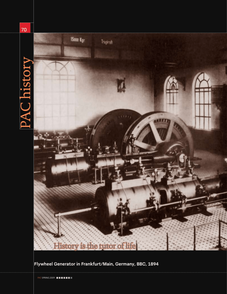
PAC history 70 History is the tutor of life Flywheel Generator in Frankfurt/Main, Germany, BBC, 1894 PAC.SPRING.2009 by Walter Schossig Protection 71 History DC Generator, Kriegstetten (CH) Power Station, Oerlikon, 1886. Biography Generators are important and expensive assets. Generator Protection The Beginning Introduction In the beginning of electrical power supply (1880-1890) the importance of switching devices was minor. Small units for illumination of a house and commercial building had been put into operation. Knife switches, strip fuses and a simple bulb for supervision of voltage were sufficient for dynamos with a power of 15…25 kW. Edison,T.A. started running the first central station and first public electric utility in New York (Pearl Street) on September 4th, 1882. At first he used three and later six 150 kW, 110 VDC, 1200 rpm "Jumbo Generators" (due to their large size). He developed a complicated lighting system with lines, distribution boards, fuses, breakers and metering devices. The first public power station in Germany with six steam machines (150 HP each) and 12 dynamos with a total power of 540 kW (110 VDC with two-wire connection) was put into operation on May10th,1885 (Berlin, Markgrafenstrasse 44). The first switching devices were more or less provisional ones due to lack of experience and limited knowledge. They have were in an empirically-manual manner and were suitable for single tasks. Such an example was the "general interrupter" in the Berlin power station which would enable an emergency cutout of the whole grid. Figure 2 shows such a makeshift construction (nominal current approximately 2000 A and 2x110 VDC. Unlocking the four clamps lets the copper ear plate fall down and interrupt the circuit. At this time DC was mostly used. Due to this and the inductance of the machines the control and extinguishing of the lightning arc when switch off occurred, was difficult even at low voltages (65…110 VDC). Developing motors and generators was a challenging task anyway- so nobody was really interested in the so called "auxiliary devices" low voltage circuit breakers. The initial switching devices originated from laboratories (mercury bowls) or from the telegraph industry (switches and push buttons). Because these devices did not meet heavy-current requirements, engineers avoided them or tried to reduce the breaking capacity with de-excitation of generators. At the time of introduction of alternating current, oil was estimated as the optimal extinguishing agent. The pioneer of alternating current, Ferranti, was the first at using oil for that purpose. He plunged the agile part of the PAC.SPRING.2009 Walter Schossig (VDE) was born in Arnsdorf (now Czech Republic) in 1941. He studied electrical engineering in Zittau (Germany), and joined a utility in the former Eastern Germany. After the German reunion the utility was renamed as TEAG, now E.ON Thueringer Energie AG in Erfurt. There he received his Masters degree and worked as a protection engineer until his retirement. He was a member of many study groups and associations. He is an active member of the working group “Medium Voltage Relaying” at the German VDE. He is the author of several papers, guidelines and the book “Netzschutztechnik [Power System Protection]”. He works on a chronicle about the history of electricity supply, with emphasis on protection and control. PAC history 72 1 Maximal automat, USA, 3 Ferranti-oil-fuse (1894) into the oil after opening the contact. Results of a short circuit in a unprotected The first high-voltage device working completely in oil was machine (appr. 1930) developed by C.L.E. Brown (one of the founders of Brown, Boveri & Cie) in Baden/Switzerland in 1897. He proposed at the headquarters Porta Volta in Milan to put an air-circuit breaker (5 kV) in a barrel of oil for testing purposes. This was successful, and a new 16-kV-breaker was developed in the same year for Paderno (with an oil hutch made of glass). Later, steel plate hutches were used. One could now protect the generator by switching it off with a circuit breaker and de-exciting it in case of a certain smell, electrical arc, or loud noises. Previously, this was not possible due to the long reaction time (Figure 3). First Generator Protection Devices The first protection devices were fuses in series with knife switches. Before that, there were fuses at the generator only, so in case of a failure the whole grid (very small at this time) was without power. After a short time it became clear that not having a three-phase trip was a disadvantage. That's why from 1885 to1890 the first automatic circuit breakers 2500 V, 50 PS, = 70 %) by Oerlikon. Figure 5 shows the were developed. One of the first automatic circuit breakers in wooden switchboard, above the interface-device ( 3 wires Germany was made by Hermann Meyer, S & H, 1886 with with a diameter of 6 mm, one of them as spare). On the left the "biggest machine circuit breaker at this time" (knife switch) and on the right the automatic short-circuiters are arranged; combined with an electromagnetic undercurrent relay (startup they are shorting the field magnets in case of a fault. They were at 10% of nominal or reverse current). This was a combination used to replace the lead fuses. „Switchboards“ of minimum- and reverse-current-automats (early relays), used for parallel operating DC generators. In the first years of high-current technology (1880- 1890) After this the first "triumvirate"-automats were a "switchyard" consisted of a DC-dynamo connected to a developed: minimum-automat; reverse-current-automat and switchboard. A board made of planks. Wood was considered maximum-automat (Figure 4) as fundamental components a good insulator at this time. In Figure 6 you can see the of the DC-generation and -distribution at this time together planks and the attached instruments, main switch and four with batteries in power stations. The task of these devices was knife-switches with stripe fuse. The word "board" (in German the switching-off during low currents, wrong direction of "Brett") is still used for terminal boxes of generators and motors currents or overcurrents. - “terminal board“ in English. A mock up circuit is sometimes The tripping was accomplished electromechanically. called a "breadboard" ("Brettschaltung"). Automatic Overcurrent Devices Several types were created. The first industrial transmission of current in Switzerland took place in 1887 with commissioning In 1885 American engineers equipped the knife switches of the DC-interconnection Kriegstetten-Solothurn ( 8 km, with overcurrent magnets (Figure 1). A click holds the knife 2 "General-Interrupter" in power station Markgrafenstrasse, Berlin, 1885 (approximately 1885) 4 Automats, open, hand-drive, S & H, 1892 1) Maximal-Automat, Nr. 5998; 2) Reverse-Current-Automat Nr. 5084; 3) Minimal Automat Nr. 5969, Startup 15 % of Nominal Current 1 PAC.SPRING.2009 2 3 73 The trip free mechanism developed in 1900, was the main progress for automatic circuit-breakers. in position "On"; replaceable-devices made of coal took the lightning arc, additional extinguishing possibilities were not prepared. C.E.L. Brown, OERLIKON, built a maximal automat as shown in Figure 7 (open position) in 1888. In case of a generator overcurrent condition, the automat starts up and shorts the excitation winding. The knife falls down and connects the moving contacts. This approach solves the challenge of interrupting high currents in case of high self-induction voltage. Later overcurrent automats had more force. The knife closed with a clamped spring (during switching on or with a weight). If the magnet tripping device operated it moved the switch into the Off-position. The smallest starting current possible was 130% of the nominal current, in normal case they have been set with a value of 150%. Automatic Undercurrent Devices The task of automatic undercurrent devices was to switch off parallel operating generators in case of a decreasing generator current to avoid a feedback current from the battery to the generator. The moment of switching off depends on the prior magnetizing current (magnetization). The higher the preload, the lower the startup value. The set point was 15% in 1882, later 5%. An unpleasant –even dangerous- behavior of some automatic undercurrent devices was a malfunction caused by rapidly decreasing currents with fast change of direction of currents due to the magnetic inertia. Reverse Current Automatic Devices Due to the uncertainty of some automatic undercurrent devices reverse current automats were used instead of them. In 1892 they could start with 20% of the nominal value. The tripping magnet was equipped with a current-and a voltage-coil. During normal operation both coils are working against each other ("differential coil"), in case of reverse current the switch trips (Figure 9). Under Voltage Tripping Device Breakdown and recovery of voltage, a daily event in early times, required the usage of devices with under voltage tripping elements. At first "automatic circuit-breakers" (Figure 17) were used. Later the devices were combined with other functions for switches. A solution for two-phase short-circuit protection with undervoltage trip was presented by V&H in the 1920's (Figure 8). Primary tripping devices, were mounted on the breaker operate mechanism with a lever. The voltage tripping device is supplied by an external voltage transformer (Figure 12). When the voltage transformer operates in the direction of infeed it is guaranteed that the circuit breaker could be switched on only in case of existing voltage. The company Dr. Paul Meyer introduced a three phase zero voltage tripping device in 1912 "Trip Free Mechanism" The trip free mechanism, developed in 1900 was the main progress for automatic circuit-breakers. This was a special design of the switch, ensuring that it fully opened before it was enabled to be to closed again. Figure 10 shows such a trip free 6 Switchboard“ of a DC-generator, Schuckert, 1890 7 1888, OERLIKON 5 Wooden switchboard in control center Kriegstetten, Oerlikon, 1886 PAC.SPRING.2009 PAC history 74 9 Principle of Reverse Switch 10 Köckner, Free tripping 8 Oil Circuit Breaker, V&H, appr. 1920 Breaker with: Primary Tripping Device and Secondary Undervoltage Tripping Device mechanism. It required a current in coil 1 before the switch could be operated. If these devices were not available, the approach was to avoid disabling of the automatic circuit-breakers in case of a trip (e.g. switch onto fault): Then, the automatic circuit-breaker and the lever switch are connected in series. When switching, the automatic circuit-breaker was first operated and then the lever switch was opened. This caused some failures due to wrong order of operation, this was reported for instance from the United States. That's why Sharpstein, S.H. required "a trip free mechanism" in 1899, realized by Emmett and Hewlett, GEC. 11 Generator-Switchboard, AEG, Vienna "Jubiläums-Gewerbeausstellung", 1888 (approximately 1900) PAC.SPRING.2009 Increase in demand on power and transmission of energy over long distances was the reason to build bigger generators. Use of Measurement Transformers Increase in demand on power and transmission of energy over long distances was the reason to build bigger generators or to operate generators and grids in parallel. This required the use of measuring transformers. It seems that the first voltage transformer had been used in the "Californian Light Company" in San Francisco in 1879. The current transformer was invented by Benischke,G. in 1898. And since 1900 relays were designed to use current transformers. Emmet,W.L.R. und Hewlett,H.E., GEC, built in 1901 oil circuit breakers with two tripping coils, directly connected to the current transformers to open the locking mechanism. Figure 16 shows an "automatic machine tripping device" with an overcurrent relay supplied by current transformers (used by AEG in power stations in 1905). The figure shows the solution with auxiliary power supply. But this breaker was manufactured with tripping coils supplied by two parallel operating current transformers. It was a logical conclusion to change the measuring devices in such a manner that the indicator also operates the contact. Nevertheless this solution was unsatisfying. The breaking capacity was poor (6 VA at 220 V) and the electric arc held the contacts together. Since the same measuring principles have been used the first relays have been quite similar to measuring devices (especially the round form Figure 19). 12 Voltage decrease tripping device, V&H, appr. 1920 75 The Swedish Company ASEA delivered the first induction relay for a water station of the Swedish Rail (16 2/3 Hz) in 1912. To cut one's own path was the decision of Voigt & Haeffner (V&H). Vogelsang, M. developed an overvoltage relay with timing element in 1902. They decided to do it like that because they did not produce current transformers themselves. Additionally Vogelsang developed an "oil circuit breaker with fuse". To change the fuse it was at first necessary to switch off the breaker before opening the cap. The history of measuring transformers will be covered in a later issue of PACWorld. Overcurrent Protection The main element of generator protection was overcurrent protection from the beginning. It protected the generator of inner damages, and was also the backup protection for all further assets such as transformers and lines. Smaller machines were equipped with direct overcurrent release, connected with a lever (Figure 13; Figure 15). The first stand-alone electromechanical relay was designed in1904. Figure 18 shows the first time-overcurrent relay made by ASEA, type TCB, manufactured in 1905. ASEA's (now ABB) first relay of induction type was delivered in 1912 to a hydropower station in the north of Sweden, built to deliver power at 16 2/3 Hz to the railway from Kiruna to Luleå, which was built to transport iron ore. This was the first electrified railway in Sweden. Overload Protection The use of thermal relays for protection of generators was introduced exclusively by BBC in Europe and was very successful. German recommendations required generators with a nominal power of more than 5000 kVA to use six resistancethermometers or thermo elements in the stator to supervise the temperature of winding. Once they were installed it was very difficult to reach them again- that's why they very often were not changed after damage. So it was the decision to supervise the temperature with thermal relays. These devices are equipped with thermo elements (heating relays with current proportional to main current delivered an image of temperature of the machine- Figure 14. The outer insulating mat "O", was working as a protection against thermal radiation. It encloses the source of heat, the measuring element and the heat storage "P". The heating element – a band made from a resistive material- heated the measuring column and the heat material storage, consisting of changeable measuring boards. The thermal time constant of the relays could be changed with the numbers of boards in 6 stages between 20 and 110 minutes. The upper scale was a display of the temperature to allow a later estimation of temperature. Additionally the relays were equipped with a tripping device. Later single pole overcurrent relays with a setting of 1.1 In and 10 s have been used for indicating overload. Short Circuit Protection To use overcurrent relays between generator and busbar in case of failures inside the generator was active only if other machines were able to deliver short circuit currents. The 13 Independent direct release HB, BBC, 1943 14 Thermal image of ST-Relays (BBC) The main element of generator protection was a overcurrent O P from the beginning. 15 16 Thermal relays Maximum On-Off HT, BBC, 1943 switch, AEG, 1905 17 "Automat", Berlin, 1891 "Automat" with Undervoltage Tripping Device, Gebrüder Naglo PAC.SPRING.2009 PAC history 76 18 First time-overcurrent relay, TCB, ASEA, 1905 power of another machine had to be as big as the power of the machine to be protected. In case of its own failure the generator delivered a huge short circuit current but this could not be detected with such a setup. That's why overcurrent relays have been installed in the neutral point of the generator. This setup was the only possibility if the generator was the single source in the grid. Figure 21 shows a three-phase overcurrent protection "S", manufactured by SIEMENS in 1936. Connecting generators and grids in parallel increased the reliability of power supply but on the other hand created 19 TOC, AEG, 1916 20 Thermal 21 Overcurrent overcurrent (ST,BBC) protection S, Siemens Pl Nr 69036G, 1914 & Pl Nr 69007 PAC.SPRING.2009 unmanageable short-circuit currents in case of failure. Sometimes the unreasonable guaranties for small voltage drops in the machine required the use of coils for the limitation of the current from generators with high short circuit power (hard machines). Later "soft" generators were used, equipped with a huge short-circuit reactance. The Swiss grid reported good experiences with the usage of a cutback of excitation to achieve a limitation of a sustained short-circuit current. All big power stations have been equipped with such devices. The automatic decrease of excitation could limit the steady-state short-circuit current to a certain value (as 1.4*Inom). After switching off the short circuit the voltages recovers. Out of step machines could be "catched". The current level in case of a short circuit sometimes reached the level of overload current. Nevertheless, in case of a malfunction of the line protection the generator overcurrent protection should trip. Solowjew,L.E., USSR, proposed in 1932 to use "undervoltage supervision". This allowed a more sensitive setup of the overcurrent startup. An overcurrent relay produced by BBC in the 1960's is shown in Figure 22. The overcurrent setting must be over the highest possible operating current. Since these devices started up with a fault in the grid already the operating time must be the biggest in the grid. If several generators are working in parallel all overcurrent relays had the same operating time. In case of terminal short-circuit of a generator there was no selectivity anymore. This was only possible if the faulty generator could be tripped faster than the other ones. Further solutions such as reverse power protection, differential protection, interwinding fault protection and earthfault protection will be covered in a later issue of this magazine. walter.schossig@pacw.org www.walter-schossig.de 22 Overcurrent Relays S1 without Housing, BBC, appr. 1960


