Substation "Horror ned ar
advertisement

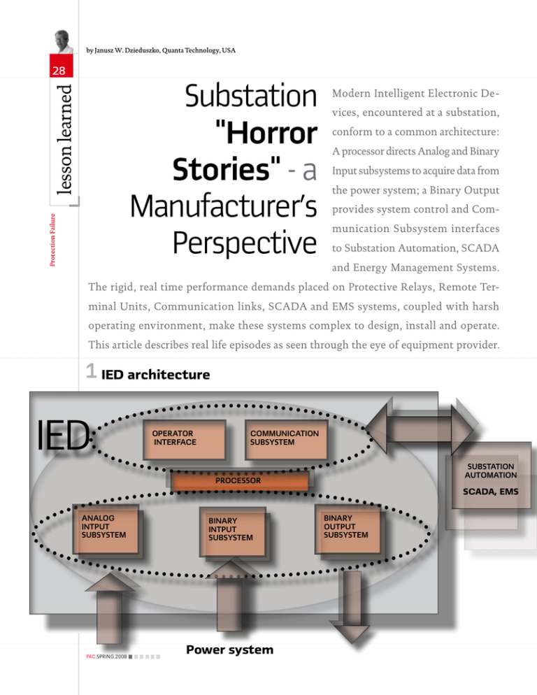
by Janusz W. Dzieduszko, Quanta Technology, USA 28 Protection Failure lesson learned Substation "Horror Stories" - a Manufacturer's Perspective Modern Intelligent Electronic Devices, encountered at a substation, conform to a common architecture: A processor directs Analog and Binary Input subsystems to acquire data from the power system; a Binary Output provides system control and Communication Subsystem interfaces to Substation Automation, SCADA and Energy Management Systems. The rigid, real time performance demands placed on Protective Relays, Remote Terminal Units, Communication links, SCADA and EMS systems, coupled with harsh operating environment, make these systems complex to design, install and operate. This article describes real life episodes as seen through the eye of equipment provider. 1 IED architecture OPERATOR INTERFACE COMMUNICATION SUBSYSTEM SUBSTATION AUTOMATION PROCESSOR SCADA, EMS ANALOG INTPUT SUBSYSTEM PAC.SPRING.2008 BINARY INTPUT SUBSYSTEM Power system BINARY OUTPUT SUBSYSTEM 29 False Breaker Trip Reporting A Supervisory Control (early 1970’s predecessor of SCADA) system at a major Electric Utility reported circuit breaker operations at several substations occurring at random, over the span of several weeks. Subsequent inspection of the breaker control equipment at those substations revealed that no breaker operations took place and a Supervisory Control equipment was providing false information. Several dozens of these systems were purchased and installed by that Utility. Naturally, the reliability of the equipment and the qualifications of the personnel involved in its design and manufacturing were seriously challenged by the Utility management. It has been mildly suggested during the meeting preceding field investigations that the equipment be put in perfect operating condition by the “end of the week” or replaced with similar product made by those “who know what they are doing”. The diagram in Figure 5 depicts a typical system configuration. The rest of the day was spent at the Master Station ( a 90” tall cabinet full of PC cards with mostly discrete transistors and indicating lights). The oscilloscope measurements indicated proper signal levels suggesting that the problem was on the RTU level. It is worth mentioning here that the understanding of the substation noise was rather sketchy in those days and the equipment tended to be overdesigned. Similar investigations were performed at the Remote Terminal Units in question. Oscilloscope measurements provided no clues. An MG-6 relay connected in “buzzer” mode was used to generate a substantial amount of noise; again no false operations were observed. As the week came to a close, the 52a wiring (see above) check was done in desperation. The RTU terminals looked fine; however, a walk to the breaker control box in the One of the most commonly used methods of system troubleshooting is “board swapping” yard was very fruitful; the corresponding terminals had loose screw connections! It was discovered later that the same problem existed at all suspected RTU locations. End result: happy Customer ! Lesson #1: Pay attention to the simplest element of your system Continuous alarm The equipment and location were the same as in the previous episode. Under normal operating conditions the alarm or change of contact status was reported by an RTU and acknowledged by a Master Station to reset the alarm. The communication links to the RTUs were 60mA loops operating at 50 bps (sic!) connected as shown in Fig ure 2. The transmit TX and receive RX devices were identical mercury wetted contact relays with plug-in octal bases. One of the RTUs reported an alarm but the Master Station acknowledgement failed to reset it, and thus an alarm condition persisted at the RTU. The system operator would dispatch a technician to the RTU who subsequently swapped TX and RX relays, thereby eliminating the problem. Several days or so later the same problem would occur, so the same approach was used and the problem cured again. Note that TX and RX relays were now in their original position! During the field trip to the substation, the real problem was determined to be a solder whisker on a printed circuit board extending to the adjacent trace, as shown in Figure 4. During abnormal system behavior with the RTU enclosure sealed, the internal temperature caused the solder whisker to expand, touching the adjacent PCB trace and disabling the alarm acknowledge circuit. Opening the enclosure to swap TX and RX relays lowered the temperature sufficiently to contract the whisker, thereby “fixing” the problem. Lesson #2: The “repair” you just made, may not have anything to do with the problem! Printed circuit board swapping One of the most commonly used methods of system troubleshooting is “board swapping”; here is another real life story. A second generation SCADA system, with computer based Master and integrated circuit CMOS RTUs, was being installed at a medium sized municipal utility. The system configuration was similar to Figure 5 with four RTUs on each communication link. The RTU conformed to Figure 1, with the processor section consisting of 3 printed circuit boards: A, B and C. A portable Master simulator was used to commission the RTUs. (Figure 3) Here is the approximate sequence of events used in initial troubleshooting: RTU #1 was verified to perform properly. 2 Janusz Dzieduszko is M.S.E.E. graduate of the Academy of Mining and Metallurgy in Cracow. He has over 40 years of experience in engineering management and design in Substation Automation. Janusz is currently Consultant with USA in Raleigh, NC. He worked with: ABB, Westinghouse,GE and BBC. He holds five patents and is authored several papers in Substation Automation. His biography is included in Marquis’ “Who is who in the World” and “Who is Who in America”. 60 mA Loop RX TX TX To Master RX To RTU PAC.SPRING.2008 Protection Failure lesson learned 30 Be aware of variables introduced during board swapping. 3 Master simulator A B C RTU #1 A B C RTU #2 RTU#2 intermittently did not respond to the simulator. The known reference set of boards(A,B,C)was inserted in RTU#2; causing the problem as in step 2. The set of boards from RTU#1 was transferred to RTU#2; causing the problem as in step 2. The set of boards from RTU#2 was t ransfer red to RT U#1; RTU#1 checked out OK! The backplane (motherboard) of RTU#2 was replaced and the problem still existed as in steps 2,3, 4! Similar situations were repeated at other RTU locations. The careful reader at this moment agrees that some mysterious events occur at those substations! Utility engineers reported later that the manufacturer’s field engineer had five sets of boards and backplanes in his automobile, and was driving at 70 mph across town (from one RTU to another) with a wild expression on his face! Here is the real problem as found many days later: To operate on a shared communication channel, the RTUs needed unique addresses. The addressing was accomplished using a compo- PAC.SPRING.2008 nent platform with vertical pins inserted in the IC socket. The top pins were jumpered with the bare wire and hand soldered. The unused connections, as determined by address decoding, were clipped off. It was found that the jumpers described above had cold solder connections causing intermittent problems. Furthermore, these innocent jumpers were subconsciously removed from the “bad” boards and transferred to the “good” boards, always remaining with RTU#2. Lesson #3: Be aware of variables introduced during board swapping. Intermittent data communication A large process control system as shown on the diagram in Figure 6 was installed. A major computer manufacturer provided main control processors, SYSTEM 370 and SYSTEM 7 and software; COMM INTFCE and RTUs were supplied by (then) a Major SCADA Company. RTU communication was via copper shielded twisted pairs with a maximum distance of 5 km. Asynchronous frequency shift (FSK) modems operating at 1800 bps, with mark and space frequencies of 1200 and 2200 Hz respectively, were used. Connection was 4 wire with separate pairs for data transmit and receive. RTU communication used popular 32-bit protocol with 2 start, 24 data, 5 CRC and 1 stop bits. SYSTEM 7 to COMM INTFCE data link was parallel with 12 bit data lines and several control lines. During final system start-up, a vicious communication problem was uncovered. Several (2 to 4) times per day COMM INTFCE reported CRC (cyclic redundancy check) errors on data acquisition; this condition existed in short bursts of 120 to 180 msec. System software invoked error recovery initiating 3 data retrieval retries and after failure, declared RTU or communication line “out of service”. This performance (even with 99.9992% availability!) was unacceptable to the user. Considerable time was invested in analysis of data communication channels. No obvious sources of suspected interference were found; all vital parameters were well within limits. The communication FSK modem was blamed, as 1800 bps operation in those days was at the cutting edge of technology. Many adjustments to compromise delay equalizer failed to improve the performance. A legal action with $6 million liability was suggested at various management levels. At that time the author was volunteered to take a look at the problem. From the very beginning he suspected factors other than those outlined above. How do you “catch” the instant of 120 msec occurring once or twice in a 24-hour period with sufficient resolution to decode 555 msec (1 bit time at 1800 bps)? (Remember, those were the days before logic analyzers, and storage oscilloscope was the best tool available.) Here is the brief description of a rather lengthy investigation process: During a trip to a local audio equipment rental facility, a stereo tape recorder and stereo earphones were obtained and connected to the communication lines: After some practice, a rhythm of “good” and “bad” communication exchanges was determined. A human ear is an excellent integrator! Occurrences of communication problems were correlated to 4 Solder whisker 31 5 Typical SCADA configuration MASTER STATION RTU RTU RTU RTU 52a 6 Process control system SYSREM 370 7 SYSREM 7 COMM INTCE RTUs Error sections of tape playback AUDIO OUT AUDIO OUT TAPE RECORDER RCVR INPUT DATA OUT FSK MODEM A B OSCILLOSCOPE PAC.SPRING.2008 Protection Failure lesson learned 32 the tape counter on tape recorder. Known sections of tape were played back as in Figure 7. Normal data retrieval sequence consisted of one 32 bit request sent to RTU, followed by up to 8 32 bit responses from RTU. Data Request RTU Response It was determined that during the communication problems one 32-bit data request was repeated as shown: Data Request RTU Response The “phantom” request, shown as shaded area, was later attributed to the race condition on the COMM INTFCE parallel to serial converter when “write” signal exceeded maximum allowable duration. As a result the receiver clock recovery mechanism was disabled and the incoming RTU response was received using transmit clock! No wonder massive CRC errors were encountered. It was later determined that the duration of 8 “write” signal was affected by SYSTEM 7 loading. To make COMM INTFCE immune to variations of this signal, a monostable multivibrator (one shot) was added, thus eliminating the entire problem. The author fondly recalls having to work 14 hours on the Bicentennial Fourth of July 1976! Lesson #4: Design your interfaces with care, protect yourself! Do not be afraid to use unconventional tools. Fiber optic noise immunity Industry’s first Integrated Substation Protection and Control system was designed as an EPRI project in early to mid 1980s using the then state of the art microprocessor 8086 16-bit technology. Due to processing limitations, (8086 operating at 6MHz and memory of 128 kbytes) multiple processors (up to 6) shared the computational loads and were configured in shared memory clusters.Figure 8 shows a simplified diagram of the system. The Station Computer provided operator interface for substation management and was connected to Protection Clusters via coaxial cable When things do not make sense, you have made a wrong assumption! Data Highway communicating at 1Mbps. Protection Clusters’ function was protection and control; Data Acquisition Units interfaced to the power system and were connected via fiber optic Data Links operating at 1Mbps to Protection Clusters. Fiber optic Clock and Arbitration Bus synchronized the system and allowed for intercluster communication for time critical control operations.The system was designed with interoperability in mind 20 years before IEC 61850; the elements shown in dotted lines were provided by another manufacturer and were successfully integrated into the system during final installation at a major 500 kV sub- Simplified diagram of the system XFMR Protection clusters BUS LINE data highway Station Computer data links Clock & arbitration bus 500 kV Yard DAU Data acquisiton units PAC.SPRING.2008 33 station.In the final phase of testing at the factory, the system suddenly started to “crash” several times per day.Extensive use of fiber optics assured very high degree of noise immunity, thus exonerating system hardware.The interaction of multiple processors in clusters was suspected and analyzed over the period of days; no obvious reasons were found. It was observed later that the crashes occurred during late morning, and were later correlated to the passing of a Mail Robot vehicle near the system. The vehicle has a motor that generates EM interference; the system hardware became a prime suspect. Very soon the problem was solved: A robot (in addition to motor) had a safety strobe light that was penetrating one of the Protection Clusters via partially open enclosure rear door. These light pulses were “read” as spurious interrupts by a fiber optic receiver left open for the integration of other manufacturer’s cluster into the system. A strategically placed piece of electrical tape cured the problem. Lesson #5: Do not take anything for granted. False system operations Some time following successful installation and integration at the substation, the system described in the previous chapter began to issue false breaker trip commands. These occurrences were rare (2 to 3 weeks apart), random, and were traced down to all protection clusters. Obviously, much energy, time, and money was invested in attempts to eliminate this unpleasant phenomenon. The complexity of the system opened the door to various theories in two basic areas: Substation noise System software bug The system passed extensive factory type testing including SWC, Fast Transient, RFI and temperature limits. Massive utilization of fiber op- tics for system interfaces eliminated a wide area of suspicion. The system was designed by software and hardware engineers with vast experience in substation requirements. Software “traps” were added to the system, logic analyzers initialized to trigger on suspected events were installed, and additional filtering and shielding were tried; no answers were obtained. The last element analyzed by the author was Analog Input card in Data Acquisition Unit. (Figure 9) The microprocessor controlled the A/D conversion process, and using precision REF inputs, provided continuous A/D calibration for temperature and component tolerance drifts. The calibration was in the form of: Where y – A/D output; a – gain; x – Analog input; b – offset.The A/D had 16-bit output, while the microprocessor was 8049 family 8-bit machine. All arithmetic operations were, therefore, using double precision arithmetic (low byte, high byte). 15 7 High byte 0 7 Low byte And a quote from the past: “Omnia autem probate quod bonum est tenete.” “Prove all things; hold fast that which is good.” I Thessalonians 5:21 A rms) for analog inputs. It is easy to compute that the input of approximately 20 mV (0.585 A rms) sets bit 7 of LOW BYTE to a “1”, thus causing the false assumption of a huge fault current (equal or greater then 30 p.u.) and subsequent system trip. Lesson #6: Pay attention to processor architecture. Avoid fixedpoint arithmetic. 0 0 The assembly language programming was used.Taking the program listings and processor reference manual home, away from the day to day distractions, after several hours of careful instruction by instruction study, the resounding EUREKA! followed. It was found that doing ax + b addition, the processor checked for possible register overflow (i.e. the result possibly exceeding 15 bit number). Bit 7 of HIGH BYTE set to “1” indicated that fact, and should result in setting the register to full scale (7FFFhex). Instead of testing that bit, bit 7 of LOW BYTE was tested in error (otherwise known as software “bug”). Full scale input to the A/D was 5 V corresponding to 30 p.u. (150 9 Analog Input FIELD INPUTS A/D MUX REF µP PAC.SPRING.2008


