RF Hardware Example: Phase Shift Keying
advertisement
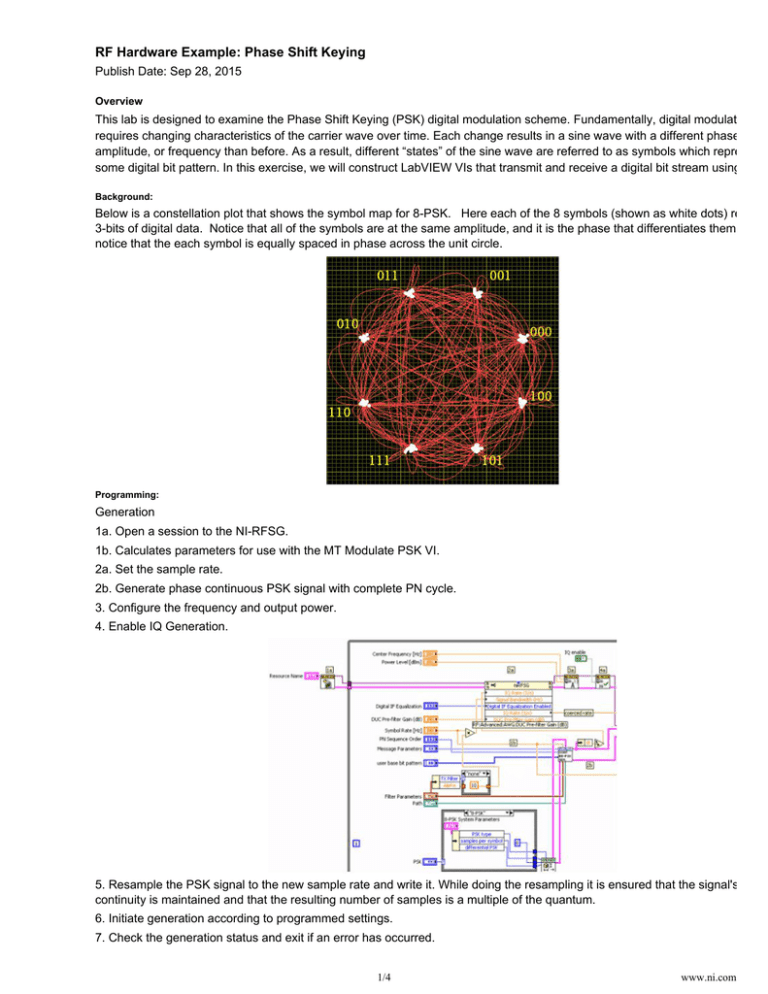
RF Hardware Example: Phase Shift Keying Publish Date: Sep 28, 2015 Overview This lab is designed to examine the Phase Shift Keying (PSK) digital modulation scheme. Fundamentally, digital modulation requires changing characteristics of the carrier wave over time. Each change results in a sine wave with a different phase, amplitude, or frequency than before. As a result, different “states” of the sine wave are referred to as symbols which represent some digital bit pattern. In this exercise, we will construct LabVIEW VIs that transmit and receive a digital bit stream using PSK Background: Below is a constellation plot that shows the symbol map for 8-PSK. Here each of the 8 symbols (shown as white dots) represe 3-bits of digital data. Notice that all of the symbols are at the same amplitude, and it is the phase that differentiates them. Also notice that the each symbol is equally spaced in phase across the unit circle. Programming: Generation 1a. Open a session to the NI-RFSG. 1b. Calculates parameters for use with the MT Modulate PSK VI. 2a. Set the sample rate. 2b. Generate phase continuous PSK signal with complete PN cycle. 3. Configure the frequency and output power. 4. Enable IQ Generation. 5. Resample the PSK signal to the new sample rate and write it. While doing the resampling it is ensured that the signal's phase continuity is maintained and that the resulting number of samples is a multiple of the quantum. 6. Initiate generation according to programmed settings. 7. Check the generation status and exit if an error has occurred. 8. Disable the output. This sets the noise floor as low as possible. 1/4 www.ni.com 8. Disable the output. This sets the noise floor as low as possible. 9. Close the session to the NI-RFSG. Acquisition 1. Initialize the downconverter and the digitizer. 2. Set the PSK system parameters. Several types of PSK are preconfigured via the case structure. You can also define your o custom type of PSK. 3. Set the reference level of the 5600 to the expected max input level, for best signal to noise. Configure the horizontal subsyste of the digitizer. The MT Configure Downconversion Settings VI takes in the user parameters and determines the correct sampl rate and number of samples to acquire. 4. Generate the filter coefficients for the demodulator. 5. Determine a bandwidth based on the input symbol rate and filter parameters. The 1.1 factor in the default case provides a sm cushion for carrier offset. 6. Acquire and downconvert (if necessary). The data coming out of the 5620 can be IF or interleaved I - Q, depending on whet the DDC is used. The data coming out of MT Convert IF to IQ is always I - Q represented as a complex signal. 7. Resample the signal. The demodulator requires an integer number of samples per symbol. MT Fractional Resample resamples the data to satisfy this condition. Set the new sample rate to Fs' = (symbol rate)*(samples per symbol). 8. Demodulate. The "recovered waveform" output of the demodulator is equivalent to the input with frequency and phase offse removed, and the first sample corresponds to an ideal symbol time. 9. Calculate measurements on the recovered waveform. 10. Format and display the trellis diagram 11. Use the Event Structure to control the loop structures. A time-out event (Event [0]) reads the "stop" button, and all loops wi exit if the "stop" = TRUE. If stop is FALSE, and there is no error, the inner loop will run again. If any controls in the middle loop change, Event [1] will fire, the inner loop will exit, and the middle loop will run again. If any controls in the outer loop change, Event [2] will fire, both the inner and middle loops will exit, and the outer loop will run again. 12. If the middle loop exits, the instrument handles and the receiver info will be closed. The new handles will be opened if the 2/4 www.ni.com 12. If the middle loop exits, the instrument handles and the receiver info will be closed. The new handles will be opened if the outer loop runs again. Customer Reviews 1 Review | Submit your review ( http://zone.ni.com/apps/utf8/nidz_display_comments.create_comment?p_title=RF+Hardware+Example%3A+Phase+Shift+Key ) PRODUCT SUPPORT COMPANY Order status and history (http://www.ni.com/status/) Submit a service request ( https://sine.ni.com/srm/app/myServiceRequests) Order by part number ( http://sine.ni.com/apps/utf8/nios.store?action=purchase_form Manuals (http://www.ni.com/manuals/) ) Drivers (http://www.ni.com/downloads/drivers/) Activate a product ( http://sine.ni.com/myproducts/app/main.xhtml?lang=en Alliance Partners (http://www.ni.com/alliance/) ) About National Instruments ( http://www.ni.com/company/) Events (http://www.ni.com/events/) Careers (http://www.ni.com/careers/) Order and payment information ( http://www.ni.com/how-to-buy/) MISSION NI equips engineers and scientists with systems that accelerate productivity, innovation, and discovery. (http://twitter.com/niglobal) ( http://www.facebook.com/NationalInstruments) ( http://www.linkedin.com/company/3433?trk=tyah) (http://www.ni.com/rss/) ( http://www.youtube.com/nationalinstruments) Contact Us (http://www.ni.com/contact-us/) (http://privacy.truste.com/privacy-seal/National-Instruments-Corporation/validation?rid=bc6daa8f-7051-4eea-b7b5-fb24dcd96d95) 3/4 www.ni.com Legal (http://www.ni.com/legal/) | © National Instruments. All rights reserved. | Site map ( http://www.ni.com/help/map.htm) 4/4 www.ni.com
