Extraction of small-diameter beams from single-component plasmas
advertisement
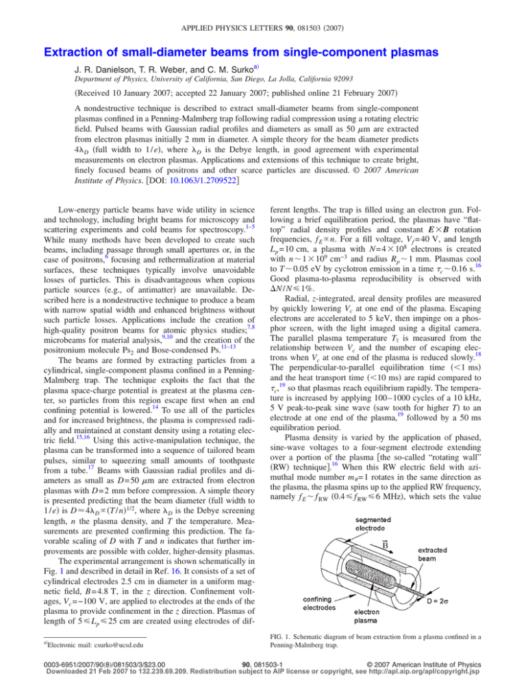
APPLIED PHYSICS LETTERS 90, 081503 共2007兲 Extraction of small-diameter beams from single-component plasmas J. R. Danielson, T. R. Weber, and C. M. Surkoa兲 Department of Physics, University of California, San Diego, La Jolla, California 92093 共Received 10 January 2007; accepted 22 January 2007; published online 21 February 2007兲 A nondestructive technique is described to extract small-diameter beams from single-component plasmas confined in a Penning-Malmberg trap following radial compression using a rotating electric field. Pulsed beams with Gaussian radial profiles and diameters as small as 50 m are extracted from electron plasmas initially 2 mm in diameter. A simple theory for the beam diameter predicts 4D 共full width to 1 / e兲, where D is the Debye length, in good agreement with experimental measurements on electron plasmas. Applications and extensions of this technique to create bright, finely focused beams of positrons and other scarce particles are discussed. © 2007 American Institute of Physics. 关DOI: 10.1063/1.2709522兴 Low-energy particle beams have wide utility in science and technology, including bright beams for microscopy and scattering experiments and cold beams for spectroscopy.1–5 While many methods have been developed to create such beams, including passage through small apertures or, in the case of positrons,6 focusing and rethermalization at material surfaces, these techniques typically involve unavoidable losses of particles. This is disadvantageous when copious particle sources 共e.g., of antimatter兲 are unavailable. Described here is a nondestructive technique to produce a beam with narrow spatial width and enhanced brightness without such particle losses. Applications include the creation of high-quality positron beams for atomic physics studies;7,8 microbeams for material analysis,9,10 and the creation of the positronium molecule Ps2 and Bose-condensed Ps.11–13 The beams are formed by extracting particles from a cylindrical, single-component plasma confined in a PenningMalmberg trap. The technique exploits the fact that the plasma space-charge potential is greatest at the plasma center, so particles from this region escape first when an end confining potential is lowered.14 To use all of the particles and for increased brightness, the plasma is compressed radially and maintained at constant density using a rotating electric field.15,16 Using this active-manipulation technique, the plasma can be transformed into a sequence of tailored beam pulses, similar to squeezing small amounts of toothpaste from a tube.17 Beams with Gaussian radial profiles and diameters as small as D = 50 m are extracted from electron plasmas with D = 2 mm before compression. A simple theory is presented predicting that the beam diameter 共full width to 1 / e兲 is D ⬇ 4D ⬀ 共T / n兲1/2, where D is the Debye screening length, n the plasma density, and T the temperature. Measurements are presented confirming this prediction. The favorable scaling of D with T and n indicates that further improvements are possible with colder, higher-density plasmas. The experimental arrangement is shown schematically in Fig. 1 and described in detail in Ref. 16. It consists of a set of cylindrical electrodes 2.5 cm in diameter in a uniform magnetic field, B = 4.8 T, in the z direction. Confinement voltages, Vc = −100 V, are applied to electrodes at the ends of the plasma to provide confinement in the z direction. Plasmas of length of 5 艋 L p 艋 25 cm are created using electrodes of difa兲 Electronic mail: csurko@ucsd.edu ferent lengths. The trap is filled using an electron gun. Following a brief equilibration period, the plasmas have “flattop” radial density profiles and constant E ⫻ B rotation frequencies, f E ⬀ n. For a fill voltage, V f = 40 V, and length L p = 10 cm, a plasma with N = 4 ⫻ 108 electrons is created with n ⬃ 1 ⫻ 109 cm−3 and radius R p ⬃ 1 mm. Plasmas cool to T ⬃ 0.05 eV by cyclotron emission in a time c ⬃ 0.16 s.16 Good plasma-to-plasma reproducibility is observed with ⌬N / N 艋 1%. Radial, z-integrated, areal density profiles are measured by quickly lowering Vc at one end of the plasma. Escaping electrons are accelerated to 5 keV, then impinge on a phosphor screen, with the light imaged using a digital camera. The parallel plasma temperature T储 is measured from the relationship between Vc and the number of escaping electrons when Vc at one end of the plasma is reduced slowly.18 The perpendicular-to-parallel equilibration time 共⬍1 ms兲 and the heat transport time 共⬍10 ms兲 are rapid compared to c,19 so that plasmas reach equilibrium rapidly. The temperature is increased by applying 100– 1000 cycles of a 10 kHz, 5 V peak-to-peak sine wave 共saw tooth for higher T兲 to an electrode at one end of the plasma,19 followed by a 50 ms equilibration period. Plasma density is varied by the application of phased, sine-wave voltages to a four-segment electrode extending over a portion of the plasma 关the so-called “rotating wall” 共RW兲 technique兴.16 When this RW electric field with azimuthal mode number m = 1 rotates in the same direction as the plasma, the plasma spins up to the applied RW frequency, namely f E ⬃ f RW 共0.4艋 f RW 艋 6 MHz兲, which sets the value FIG. 1. Schematic diagram of beam extraction from a plasma confined in a Penning-Malmberg trap. 0003-6951/2007/90共8兲/081503/3/$23.00 90, 081503-1 © 2007 American Institute of Physics Downloaded 21 Feb 2007 to 132.239.69.209. Redistribution subject to AIP license or copyright, see http://apl.aip.org/apl/copyright.jsp 081503-2 Appl. Phys. Lett. 90, 081503 共2007兲 Danielson, Weber, and Surko FIG. 2. 共Color online兲 Normalized areal density profiles of beams extracted from an electron plasma with n = 1 ⫻ 109 cm−3 at temperatures of 共쎲兲 1.0, 共䉭兲 0.2, and 共䉮兲 0.04 eV. Solid lines are Gaussian fits, as described by Eq. 共2兲. The dashed line is the areal density of the initial plasma. of n throughout the plasma.16 In a given experiment, either the procedure for changing temperature or the procedure for changing density is employed, but not both. The RW compression does produce heating,16 so in this case, both T and n change. Beams are extracted using a square-wave voltage pulse Vex to lower the trapping potential at one end of the plasma, thus allowing particles near the 共radial兲 plasma center to exit the trap.18,20,21 The extraction-pulse duration 共tex ⬃ 5 s兲 is greater than the axial bounce time 共i.e., b ⬃ 1.5 s兲,15 so that all electrons with energies greater than the confinement potential escape, but tex is kept short enough to avoid radial transport or instabilities during extraction.22 The number of extracted beam particles Nb is varied by changing Vex. This process of RW compression and extraction can be repeated for efficient use of the plasma. Radial beam profiles are measured using the digital camera, as described above. Shown in Fig. 2 are areal density profiles for three plasma temperatures. For an equilibrium, single-component plasma with L p Ⰷ RW Ⰷ R p, the plasma potential can be written as 共r兲 = 共0兲 − 共T / e兲共r / 2D兲2. Assuming all particles that can escape do so, the areal density of the ejected beam n共r兲 can be found by integrating the Maxwellian distribution over energies, Emin 艌 −e关Vc − Vex − 共r兲兴. Defining the scaled confinement potential A ⬅ −共e / T兲关Vc − Vex − 共0兲兴, n共r兲 = n0 erfc关A + 共r/2D兲2兴1/2 , FIG. 3. Log-log plot of the measured beam half width from a fit to Eq. 共2兲 as a function of the Debye length D. The solid line corresponds to = 2D. and n 共in units of 1010 cm−3兲 from 0.06 to 2.2—factors of 40 and 37, respectively. Thus, over a wide range of parameters, is proportional to D. Shown in Fig. 4 is as a function of the fraction  = Nb / N of the beam extracted for two plasma temperatures. Equation 共2兲 predicts ⬇ 2.0D, while direct calculation from Eq. 共1兲 for relevant values of the confinement potential A predicts a 1 / e half width of 1.9D. The measurements indicate 2.0艋 / D 艋 2.1. The small discrepancy of 艋0.2D 共i.e., 艋10%兲 is not understood. The maximum value of  for minimum width 共i.e., ⬇ 2.0D兲 is in the range of 0.01艋 m 艋 0.1 and is smaller at lower T. A plasma with N = 109 could produce a train of ⬃23, 5 s duration, 1 A current pulses 共3 ⫻ 107 particles per pulse兲 at a repetition rate of ⬃100 Hz 共i.e., using 70% of the plasma before refilling17兲. While the beams described here are in a strong magnetic field 共B = 4.8 T兲, they can be extracted from the field 共e.g., for further electrostatic manipulation兲.6,23 The beam emittance is given by * ⬵ 共⌬E⬜/E0兲1/2关1 + 共/2c兲兴, 共3兲 where E0 and ⌬E⬜ are the beam energy and perpendicular energy spread, respectively, and c is the cyclotron radius.23 共1兲 where erfc is the complimentary error function. For small charge pulses 共i.e., A 艌 2兲, n共r兲 ⬇ n0G共A兲exp关− 共r/兲2兴, 共2兲 exp关−A兴, and = 2D. Equation 共2兲 is where G共A兲 = 共A兲 a key result. The radial profile is approximately a Gaussian with half width to 1 / e, ⬇ 2D. The beams width is due to the parabolic dependence of 共r兲 on r in the constant-density plasma. For small charge pulses is independent of Vex, while the beam intensity can be set by Vex 关i.e., through G共A兲兴. As shown in Fig. 2, the Gaussian radial profiles predicted by Eq. 共2兲 are in good agreement with the data. Shown in Fig. 3 is the measured beam half width as a function of D. For these data, T 共in eV兲 was varied from 0.05 to 2.0, −1/2 FIG. 4. 共Color online兲 Measured beamwidths as a function of the fraction of particles,  = Nb / N, extracted from a 共쎲兲 1 eV and a 共䉭兲 0.2 eV plasma with N = 4 ⫻ 108 electrons. Sample radial profiles are shown in Fig. 2. Arrows mark = 2D and the plasma radius. Downloaded 21 Feb 2007 to 132.239.69.209. Redistribution subject to AIP license or copyright, see http://apl.aip.org/apl/copyright.jsp 081503-3 Starting with a 30 K plasma with n = 3 ⫻ 1010 cm−3 at B = 4.8 T, extraction at B = 5 ⫻ 10−4 T would result in = 0.5 mm, ⌬E⬜ = 10 meV, and a parallel energy spread ⌬E储 ⬇ 3 meV. This is superb compared to the best electrostatic positron beams in use for atomic physics studies8 and would admit to further electrostatic brightness enhancement.6 In this letter, we have described a nondestructive technique to brightness-enhanced particle beams, particularly useful for scarce particles such as antimatter.24 Since the ability to create positron plasmas with parameters very similar to those used here has been established,25 this technique is directly applicable to positrons. The limits of this technique have yet to be established. For example, densities ⬃1011 cm−3 and temperatures 艋10 K 共Refs. 13, 16, and 25兲 would result in beamwidths 艋1 m. Since n is determined by f RW, measurement of could also be used to determine plasma temperature. This might be particularly useful at low temperatures where other techniques have limited resolution.19,25 The authors wish to acknowledge helpful conversations with C. F. Driscoll, who first pointed out to them the plasmacenter extraction concept, and with R. G. Greaves. The authors thank E. A. Jerzewski for expert technical assistance. This work is supported by the NSF, Grant No. PHY 03-54653. 1 Appl. Phys. Lett. 90, 081503 共2007兲 Danielson, Weber, and Surko A. David, G. Kogel, P. Sperr, and W. Triftshauser, Phys. Rev. Lett. 87, 067402 共2001兲. 2 C. M. Surko and R. G. Greaves, Phys. Plasmas 11, 2333 共2004兲. 3 Y. Yamazaki, Mater. Sci. Forum 445–446, 430 共2004兲. 4 W. E. King, G. H. Campbell, A. Frank, B. Reed, J. F. Schmerge, B. J. Siwick, B. C. Stuart, and P. M. Weber, J. Appl. Phys. 97, 111101 共2005兲. 5 P. Hommelhoff, Y. Sortais, A. Aghajani-Talesh, and M. A. Kasevich, Phys. Rev. Lett. 96, 077401 共2006兲. A. P. Mills, Jr., Appl. Phys. 23, 189 共1980兲. 7 M. Charlton and J. W. Humberston, Positron Physics 共Cambridge University Press, Cambridge, 2001兲. 8 C. M. Surko, G. F. Gribakin, and S. J. Buckman, J. Phys. B 38, R57 共2005兲. 9 A. P. Mills, Jr., Science 218, 335 共1982兲. 10 P. J. Schultz and K. G. Lynn, Rev. Mod. Phys. 60, 701 共1988兲. 11 A. P. Mills, Jr. and P. M. Platzman, in New Directions in Antimatter Chemistry and Physics, edited by C. M. Surko and F. A. Gianturco 共Kluwer, Dordrecht, 2001兲, p. 115. 12 A. P. Mills, Jr., Nucl. Instrum. Methods Phys. Res. B 192, 107 共2002兲. 13 D. B. Cassidy, S. H. M. Deng, R. G. Greaves, T. Maruo, N. Nishiyama, J. B. Snyder, H. K. Tanaka, and A. P. Mills, Jr., Phys. Rev. Lett. 95, 195006 共2005兲. 14 C. F. Driscoll, Phys. Rev. Lett. 64, 645 共1990兲. 15 J. R. Danielson and C. M. Surko, Phys. Rev. Lett. 95, 035001 共2005兲. 16 J. R. Danielson and C. M. Surko, Phys. Plasmas 13, 055706 共2006兲. 17 For constant beam-pulse characteristics, one would convert most of the plasma 共e.g., 70%兲 into beam pulses, then replenish the plasma. 18 D. L. Eggleston, C. F. Driscoll, B. R. Beck, A. W. Hyatt, and J. H. Malmberg, Phys. Fluids B 4, 3432 共1992兲. 19 B. R. Beck, J. Fajans, and J. H. Malmberg, Phys. Plasmas 3, 1250 共1996兲. 20 J. Aoki, Y. Kiwamoto, and Y. Kawai, Phys. Plasmas 13, 112109 共2006兲. 21 G. W. Hart and B. G. Peterson, Phys. Plasmas 13, 022101 共2006兲. 22 D. B. Cassidy, S. H. M. Deng, and A. P. Mills, Jr., Nucl. Instrum. Methods Phys. Res. B 248, 121 共2006兲. 23 R. G. Greaves and C. M. Surko, Nucl. Instrum. Methods Phys. Res. B 192, 90 共2002兲. 24 Where copious particle sources exist, sacrificial techniques are available to produce cold bright beams superior to those described here 共e.g., for electrons, see Refs. 4 and 5兲. 25 L. V. Jorgensen, M. Amoretti, G. Bonomi, P. D. Bowe, C. Canali, C. Carraro, C. L. Cesar, M. Charlton, M. Doser, A. Fontana, M. C. Fujiwara, R. Funakoshi, P. Genova, J. S. Hangst, R. S. Hayano, A. Kellerbauer, V. Lagomarsino, R. Landua, E. Lodi Rizzini, M. Macri, N. Madsen, D. Mitchard, P. Montagna, A. Rotondi, G. Testera, A. Variola, L. Venturelli, D. P. van der Werf, and Y. Yamaz, Phys. Rev. Lett. 95, 025002 共2005兲. 6 Downloaded 21 Feb 2007 to 132.239.69.209. Redistribution subject to AIP license or copyright, see http://apl.aip.org/apl/copyright.jsp

