Document 10906117
advertisement

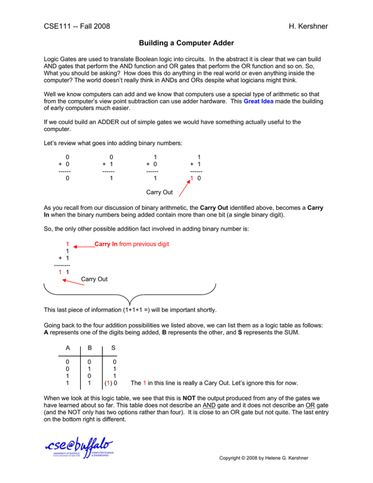
CSE111 -- Fall 2008 H. Kershner Building a Computer Adder Logic Gates are used to translate Boolean logic into circuits. In the abstract it is clear that we can build AND gates that perform the AND function and OR gates that perform the OR function and so on. So, What you should be asking? How does this do anything in the real world or even anything inside the computer? The world doesn’t really think in ANDs and ORs despite what logicians might think. Well we know computers can add and we know that computers use a special type of arithmetic so that from the computer’s view point subtraction can use adder hardware. This Great Idea made the building of early computers much easier. If we could build an ADDER out of simple gates we would have something actually useful to the computer. Let’s review what goes into adding binary numbers: 0 + 0 -----0 0 + 1 -----1 1 + 0 -----1 1 + 1 -----1 0 Carry Out As you recall from our discussion of binary arithmetic, the Carry Out identified above, becomes a Carry In when the binary numbers being added contain more than one bit (a single binary digit). So, the only other possible addition fact involved in adding binary number is: 1 1 + 1 -------1 1 Carry In from previous digit Carry Out This last piece of information (1+1+1 =) will be important shortly. Going back to the four addition possibilities we listed above, we can list them as a logic table as follows: A represents one of the digits being added, B represents the other, and S represents the SUM. A B S 0 0 1 1 0 1 0 1 0 1 1 (1) 0 The 1 in this line is really a Cary Out. Let’s ignore this for now. When we look at this logic table, we see that this is NOT the output produced from any of the gates we have learned about so far. This table does not describe an AND gate and it does not describe an OR gate (and the NOT only has two options rather than four). It is close to an OR gate but not quite. The last entry on the bottom right is different. Copyright © 2008 by Helene G. Kershner CSE111 -- Fall 2008 H. Kershner Building a Computer Adder In an OR gate the logic table is: AB 0 0 1 1 S 0 1 0 1 0 1 1 1 When describing the OR gate we could say: When “OR”ing two binary digits together If either A or B is 1 the result is 1. In the table described earlier which contains the results of binary addition we could say: A B S 0 0 1 1 0 1 0 1 0 1 1 0 When ???ing two binary digits together, If either A or B, but not both, are 1 the result is 1. Computer architects have created a special gate called the Exclusive OR (XOR) gate to represent the table above. So the Exclusive OR (XOR) states: When “XOR”ing two binary digits together If either A or B, but not both, are 1 the result is 1. This gate is built this using only combinations of the three gates we already know (NOT, AND, OR.) Let’s test the inputs from the logic table on the Exclusive OR (XOR) circuit. Exclusive OR (XOR) ( ) A = 0, B = 0 Copyright © 2008 by Helene G. Kershner CSE111 -- Fall 2008 H. Kershner Building a Computer Adder A = 0, B = 1 We can check all four possibilities this way. This circuit exactly and correctly duplicates the logic table created from our binary additions. The above circuitry is all bundled together into a single eXclusive OR (XOR) symbol: Notice that an xOR gate does correct binary addition for exactly one bit. BUT, we also know that the carry out information is ignored. Clearly, while this is a good first step it does not complete the job in creating a binary adder. More circuits are needed. Let’s examine the addition of two binary numbers with more bits (in this example there is no sign bit involved). 1 0 1 0 1 + 0 1 1 0 0 ----------------------- The leading 0 was placed in the example so that we always have two bits listed in our addition problem. Remember, keeping track of the CARRY is the only difficult part of binary arithmetic. 1 1 + 1 1 0 1 0 1 01 1 0 1 ----------------------1 0 0 0 1 1 Copyright © 2008 by Helene G. Kershner CSE111 -- Fall 2008 H. Kershner Building a Computer Adder The red 1’s above our example’s first binary number are the carry digits. Looking at this one column at a time we know that there are only four possibilities A B Sum Carry Out 0 0 1 1 0 1 0 1 0 1 1 0 0 0 0 1 Looking at this as a truth table: Sum = A B (A xOR B) Carry Out = AB ( A AND B) Therefore, for single digit addition, our circuit could be drawn as: This is fine as far as it goes BUT, going back to our binary addition problem, we find that in reality we are not adding two bits, and getting a two bit answer. Something different is going on. What really happens is that our Carry Out bit, becomes the Carry In bit for the next column’s addition. 1 1 0 1 0 1 + 0 1 1 0 1 ----------------------1 0 0 0 1 0 1 carry in carry out In fact, we could represent our entire addition problem as either having a 0 or a 1 carrying out of each addition, and acting as the carry in for the next column. + 1 1 1 0 1 0 1 0 1 0 1 0 0 1 1 0 1 ----------------1 0 0 0 1 0 0 1 1 1 0 1 carry in A B S carry out Copyright © 2008 by Helene G. Kershner CSE111 -- Fall 2008 H. Kershner Building a Computer Adder Notice, that while we think we are adding two numbers together, what we are really doing is adding 3-bits together (including our carry in) and getting an answer that is 2-bits (including our carry out) . A complete or “full” adder performs operations on 3 bits, Cin, A, B. A full adder produces a Sum and a Carry Out. The truth table that represents all the possible outcomes of these bits would look like this: Cin A B Sum Cout 0 0 0 0 1 1 1 1 0 0 1 1 0 0 1 1 0 1 0 1 0 1 0 1 0 1 1 0 1 0 0 1 0 0 0 1 0 1 1 1 From the truth table the circuit is not obvious. Let’s look at the circuit. Half Adder (1) Half Adder (2) Sum (Half Adder 1) A B XOR XOR Cin AND Sum Carry Out (Half Adder 2) AND Carry Out OR Carry Out (Half Adder 1) Sum = (Cin (A B)) Cout = (A B)(Cin) + AB Copyright © 2008 by Helene G. Kershner CSE111 -- Fall 2008 H. Kershner Building a Computer Adder To really perform arithmetic, a series of full adders need to be strung together to add all of the bits in our binary number. As the machine is being built, the manufacturer determines exactly how much hardware is available. Commonly this is 8-bits, 16-bits, and so on. The full adder works is capable of adding any binary A with B and accurately keeping track of any Carry In and any Carry Out of that addition. When solving an addition problem, the initial Carry In is set to zero (0). However, the full adder solves exactly one column in our addition problem. To completely solve a binary addition problem a series of full adders need to be “chained” together one for each digit in the problem. If we wanted to add the binary numbers 1012 with 0112 we would work as follows: Copyright © 2008 by Helene G. Kershner CSE111 -- Fall 2008 H. Kershner Building a Computer Adder 0 1 0 1 + 0 1 1 0 1 Carry In A B Sum Carry Out If you trace your values through the circuit above you can see how the circuit made up of a series of full adders solves the addition problem. Note the Sum which is the output of each column is what is written out to the computer output device (usually the monitor). Copyright © 2008 by Helene G. Kershner


