Drip irrigation scheduling
advertisement
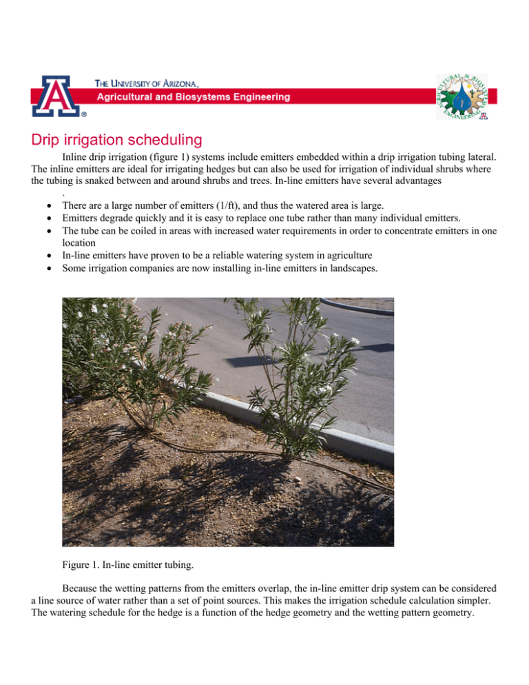
Drip irrigation scheduling Inline drip irrigation (figure 1) systems include emitters embedded within a drip irrigation tubing lateral. The inline emitters are ideal for irrigating hedges but can also be used for irrigation of individual shrubs where the tubing is snaked between and around shrubs and trees. In-line emitters have several advantages . • There are a large number of emitters (1/ft), and thus the watered area is large. • Emitters degrade quickly and it is easy to replace one tube rather than many individual emitters. • The tube can be coiled in areas with increased water requirements in order to concentrate emitters in one location • In-line emitters have proven to be a reliable watering system in agriculture • Some irrigation companies are now installing in-line emitters in landscapes. Figure 1. In-line emitter tubing. Because the wetting patterns from the emitters overlap, the in-line emitter drip system can be considered a line source of water rather than a set of point sources. This makes the irrigation schedule calculation simpler. The watering schedule for the hedge is a function of the hedge geometry and the wetting pattern geometry. Instead of calculating a watering time based on the entire hedge, it is simpler to calculate based on a length of hedge equal to the distance along the tubing between two emitters. • • • • Calculate plant water use (LPD/emitter) – Where LPD = Liters per day used by the hedge for a distance equal to the emitter spacing. Calculate soil water storage (S / emitter) – Where S = volume of usable water (liters) in soil in wetted area for each emitter. Calculate days between irrigation (S/LPD) Calculate irrigation run time (S/Q) – Where Q = emitter flow rate (LPH) The evapotranspiration rate (LPD) for a length of hedge equal to the distance between 2 emitters is calculated as follows (figure 2). ⎞ ⎛ ET mm ⎞⎛ m ⎛ 1,000 L ⎞ ⎟⎟(H * L )⎜ ⎟⎟⎜⎜ LPD = ⎜⎜ ⎟ = ET * H * L 3 ⎝ m ⎠ ⎝ day ⎠⎝ 1,000 mm ⎠ (1) where LPD L H ET = = = = evapotranspiration per emitter, liters per day, length between emitters, m, hedge (plant) width, m, depth of evapotranspiration, mm. Hedge geometry Hedge boundary H/2 Emitter Drip tubing L H/2 Hedge boundary Figure 2. Parameters used to calculate ET for hedge. The equation to calculate water storage capacity per emitter is similar to equation 1 except that the width of the wetted area is used instead of the width of the hedge (figure 3). Wetted area geometry Wetted boundary W/2 Emitter Drip tubing L W/2 Wetted boundary Figure 3. Parameters used to calculate soil water storage. ⎛ AWHC % ⎞ ⎛ 1,000 L ⎞ ⎟⎟ * MAD * ⎜ S = L * W * Z * ⎜⎜ ⎟ = 10 LWZ * AWHC % * MAD (2) 3 ⎝ m ⎠ ⎝ 100 % ⎠ where W = wetted width Example. Calculate the watering schedule for an oleander hedge during summer in Flagstaff. Oleanders are a medium water use plant so assume that ET = 3 mm/day. However, they can survive on very little water so assume that the MAD is 1.0. Assume that rooting depth, Z, is 2 m. The oleander hedge width, H, is 1.5 m. The distance between emitters, W, is 0.3 m. Emitter flow rate is 4 LPH. Wetted width from emitters is 0.8 m Clay loam soil Calculate plant water use (LPD/emitter) LPD = ET * H * W = 3 mm/day * 1.5 m * 0.3 m = 1.35 LPD Calculate soil water storage (S / emitter) S = 10 LWZ * AWHC % * MAD = 10 * 0.3 * 0.8 * 2 *18 * 1 = 86 L Calculate days between irrigation (S/LPD) Days = S / LPD = 86 / 1.35 = 64 days Calculate irrigation run time (S/Q) Hours = S / LPH = 86 L / 4 LPH = 21 hours. The system should run for approximately 1 day every 2 months.
