Instructions for the Installation of Cathode Strip Chamber Cooling Plates Tools Needed
advertisement

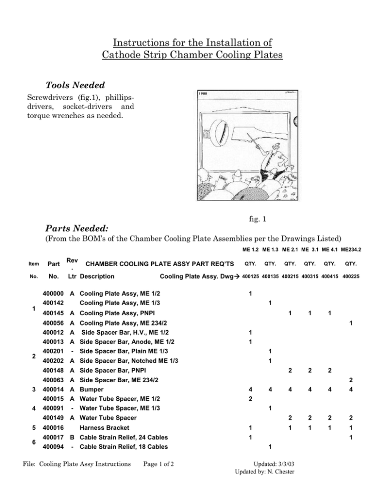
Instructions for the Installation of Cathode Strip Chamber Cooling Plates Tools Needed Screwdrivers (fig.1), phillipsdrivers, socket-drivers and torque wrenches as needed. fig. 1 Parts Needed: (From the BOM’s of the Chamber Cooling Plate Assemblies per the Drawings Listed) ME 1.2 ME 1.3 ME 2.1 ME 3.1 ME 4.1 ME234.2 Item Part No. No. 1 Rev QTY. QTY. QTY. QTY. QTY. QTY. CHAMBER COOLING PLATE ASSY PART REQ’TS . Ltr Description Cooling Plate Assy. Dwg 400125 400135 400215 400315 400415 400225 400000 A Cooling Plate Assy, ME 1/2 400142 Cooling Plate Assy, ME 1/3 1 1 400145 A Cooling Plate Assy, PNPI 1 1 1 400056 A Cooling Plate Assy, ME 234/2 400012 A Side Spacer Bar, H.V., ME 1/2 400013 A Side Spacer Bar, Anode, ME 1/2 2 400201 - 1 1 1 Side Spacer Bar, Plain ME 1/3 1 400202 A Side Spacer Bar, Notched ME 1/3 1 400148 A Side Spacer Bar, PNPI 2 2 2 4 4 4 4 2 2 2 2 1 1 1 1 400063 A Side Spacer Bar, ME 234/2 3 4 2 400014 A Bumper 4 400015 A Water Tube Spacer, ME 1/2 2 400091 - Water Tube Spacer, ME 1/3 4 1 400149 A Water Tube Spacer 5 6 400016 Harness Bracket 1 400017 B Cable Strain Relief, 24 Cables 1 400094 - Cable Strain Relief, 18 Cables File: Cooling Plate Assy Instructions Page 1 of 2 1 1 Updated: 3/3/03 Updated by: N. Chester 400141 - Cable Strain Relief, 42 Cables 1 1 1 7 400039 - Scr, M6 SHCS x 14mm lg., SS 8 8 400040 - Washer, M6 ribbed, ZPS 8 9 10 10 10 8 9 10 10 10 8 9 400041 B Scr, Flat Hd Phil ZPS M4x0.7 - 12mm lg 4 4 4 4 4 4 10 400043 A Scr, Pan Hd Phil ZPS M5x0.8 - 10mm lg, Hose Clamp 2 2 2 2 2 2 11 400044 A Scr, Pan Hd Phil ZPS M5x0.8 - 12mm lg, Plate Mtg 4 2 4 4 4 4 11 400062 A Scr, M6 PHM x 16mm lg., ZPS, Plate Mtg 12 400045 - Scr, M6 SHC x 10mm lg., SS 2 6 3 3 3 2 13 400046 - Scr, M6 SHC x 20mm lg., SS 6 5 6 6 6 6 14 400054 A Scr, Hex Wash Hd Thd Form ZPS M6x1.0 - 25 mm lg 10 10 10 10 16 15 400150 - Clamp, Loop, cushion, 0.5 w x .75 od x .265 hole 2 2 2 2 2 16 400154 - Scr, SHC, SS M6x1.0 - 30mm lg, AFEB Cab S/R Clamp 1 1 1 17 400173 A Strain Relief Plate, ME 1/2,ME 234/2 400198 - 1 1 Strain Relief Plate, PNPI 18 400174 A Spacer, 3/4" OD x 1/2" lg, Plastic 19 400199 2 Strain Relief "L" Post 4 6 1 1 1 4 4 4 1 1 1 4 Installation procedure 1) Obtain Cooling Plate Assembly (item # 1 ). 2) Install Bumpers (item # 3) with screws (item # 9) on Cooling Plate Assembly (item # 1). Hand tightness is sufficient. 3) Install Water Tube Spacer (item # 4) with screw (item # 11) on chamber Upper Cathode Extrusion. Torque screws to 50-60 in.lb. 4) Place Side Spacer Bars (item # 2) on Chamber side extrusions, place the Cooling plate on the Spacer Bars and secure the Cooling Plates with screws (item # 7) and washers (item # 8). Torque screws to 40-50 in.lb. 5) Slide the Aluminum Cushioned Clamp (item # 15) around the 370 flare fitting of the Water Hose Assemblies and secure them in place with screws (item # 10). Hand tightness is sufficient. Note: Never, ever, modify or touch the 37 0 barb fitting connecting the water hose to the copper tube on the cooling plate. The system can be guaranteed to be leak-proof only if no mechanical modification is performed on the 370 barb fitting. 6) Install the appropriate AFEB Cables Strain Relief (item # 6) and Harness Brackets (item # 5) with their appropriate screws (items # 12, # 13 and # 16 as needed). Hand tightness is sufficient. Note: Finalize and complete the assembly of the AFEB strain relief only after the installation of the AFEB cables 7) Remove 4 (four) 16 mm long screws (part # 368069) on the HV Side Panel in the position indicated on the Cooling Plate Assy Kit Drawing. Install the Plastic Spacers (item # 18) and the Strain Relief Plate (item # 17) securing them in position with 25 mm long thread forming screws (item # 14). Torque screws to 50-60 in.lb. 8) Where applicable, attach the “L” shaped strain relief posts (item # 19) in place using the screws (item # 12). Hand tight is sufficient. File: Cooling Plate Assy Instructions Page 2 of 2 Updated: 3/3/03 Updated by: N. Chester


