DEVICE TOPIC THEORETICAL BACKGROUND
advertisement
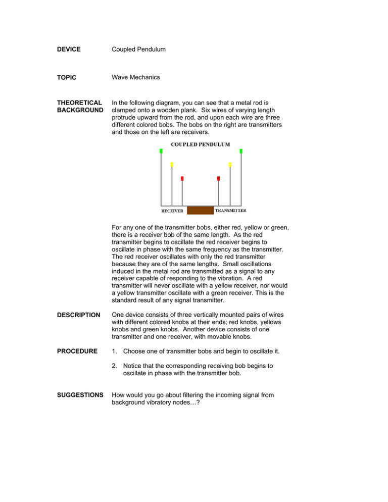
DEVICE Coupled Pendulum TOPIC Wave Mechanics THEORETICAL BACKGROUND In the following diagram, you can see that a metal rod is clamped onto a wooden plank. Six wires of varying length protrude upward from the rod, and upon each wire are three different colored bobs. The bobs on the right are transmitters and those on the left are receivers. For any one of the transmitter bobs, either red, yellow or green, there is a receiver bob of the same length. As the red transmitter begins to oscillate the red receiver begins to oscillate in phase with the same frequency as the transmitter. The red receiver oscillates with only the red transmitter because they are of the same lengths. Small oscillations induced in the metal rod are transmitted as a signal to any receiver capable of responding to the vibration. A red transmitter will never oscillate with a yellow receiver, nor would a yellow transmitter oscillate with a green receiver. This is the standard result of any signal transmitter. DESCRIPTION One device consists of three vertically mounted pairs of wires with different colored knobs at their ends; red knobs, yellows knobs and green knobs. Another device consists of one transmitter and one receiver, with movable knobs. PROCEDURE 1. Choose one of transmitter bobs and begin to oscillate it. 2. Notice that the corresponding receiving bob begins to oscillate in phase with the transmitter bob. SUGGESTIONS How would you go about filtering the incoming signal from background vibratory nodes…?


